Gradient Amplifier
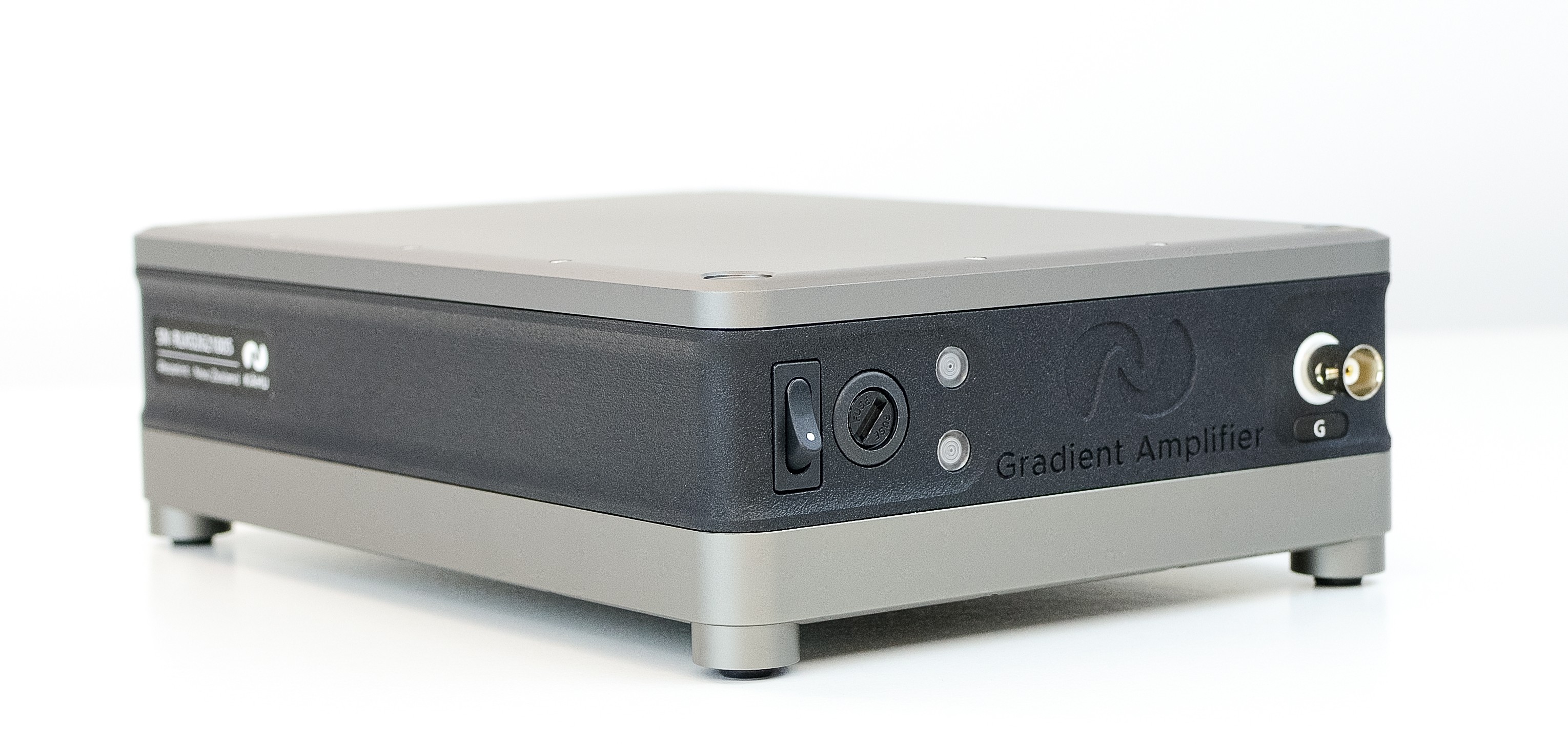
Gradient Amplifier Module Front
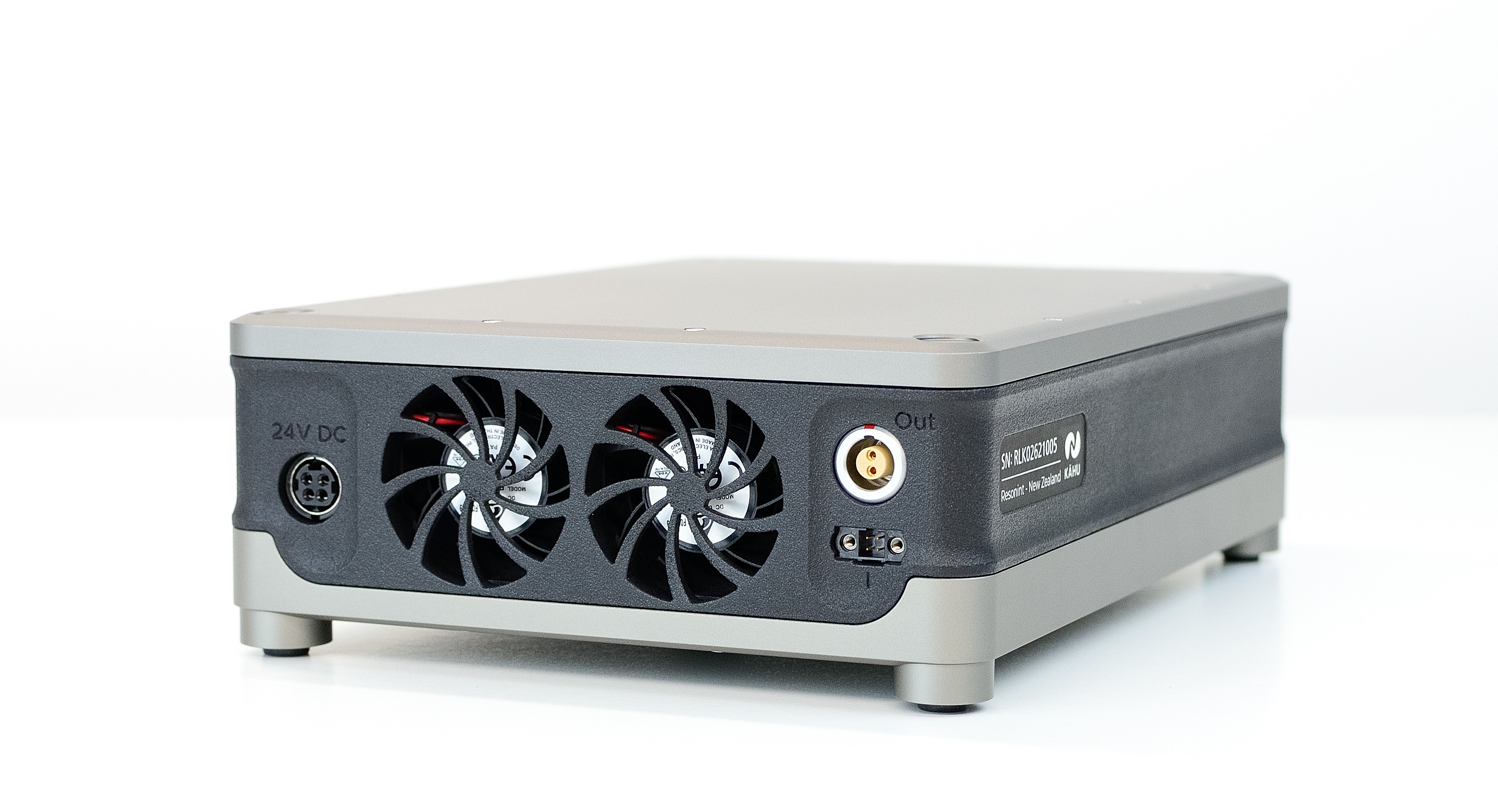
Gradient Amplifier Module Rear
The Gradient Amplifier module can be used with Kāhu to drive a single gradient coil with a controlled-current output of up to 10 A.
Connections
On front of the module you will find the BNC connector for attaching the gradient control signal from Kāhu. Additionally you will find the on/off power switch and the indicator lights. The top light will illuminate green when the module is powered on, while the bottom light will illuminate blue when the amplifier is enabled by the interlock or will illuminate red to indicate an error.
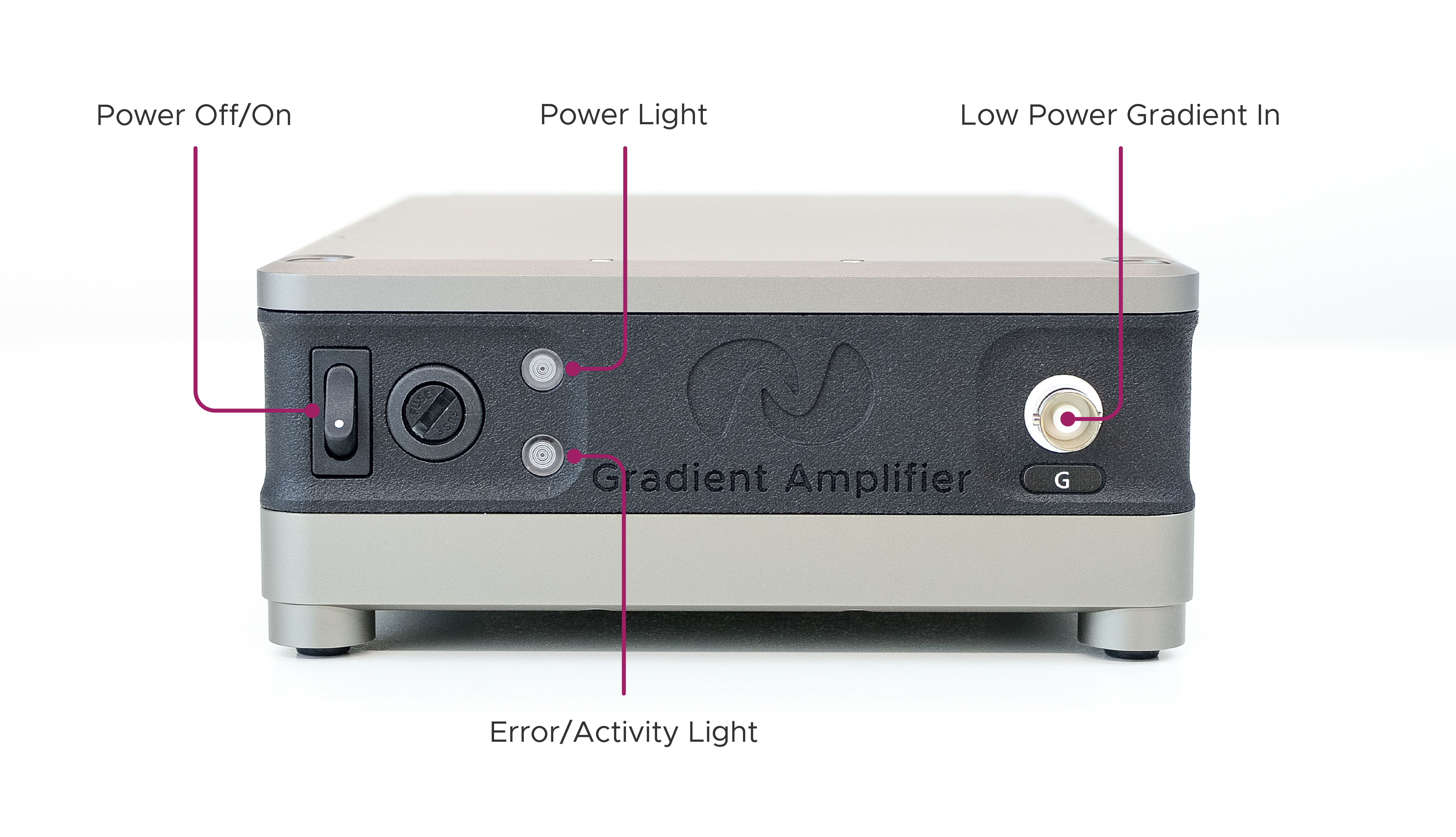
Front Controls, Connectors & Indicators
The ports for the 24 V power input, high power gradient output and interlock can be found at the rear of the module.
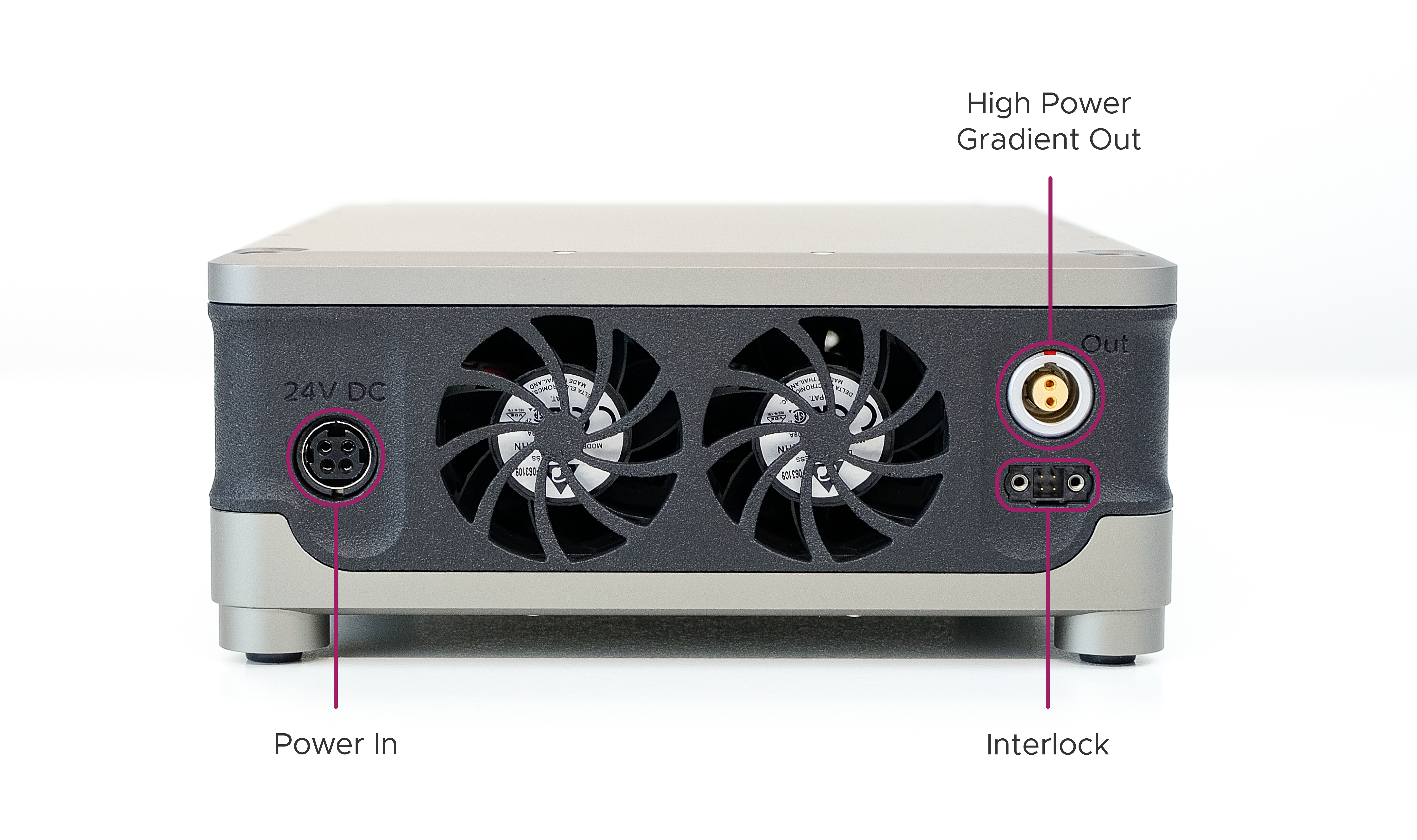
Rear Connectors
Setup Guide
This section will guide you through the steps required to connect and power the Gradient Amplifier Module with the Kāhu Spectrometer.
Warning
Ensure the Gradient Amplifier module is OFF during Kāhu power up and shutdown and when changing RF connections.
Step 1 - Rear Cable Connections
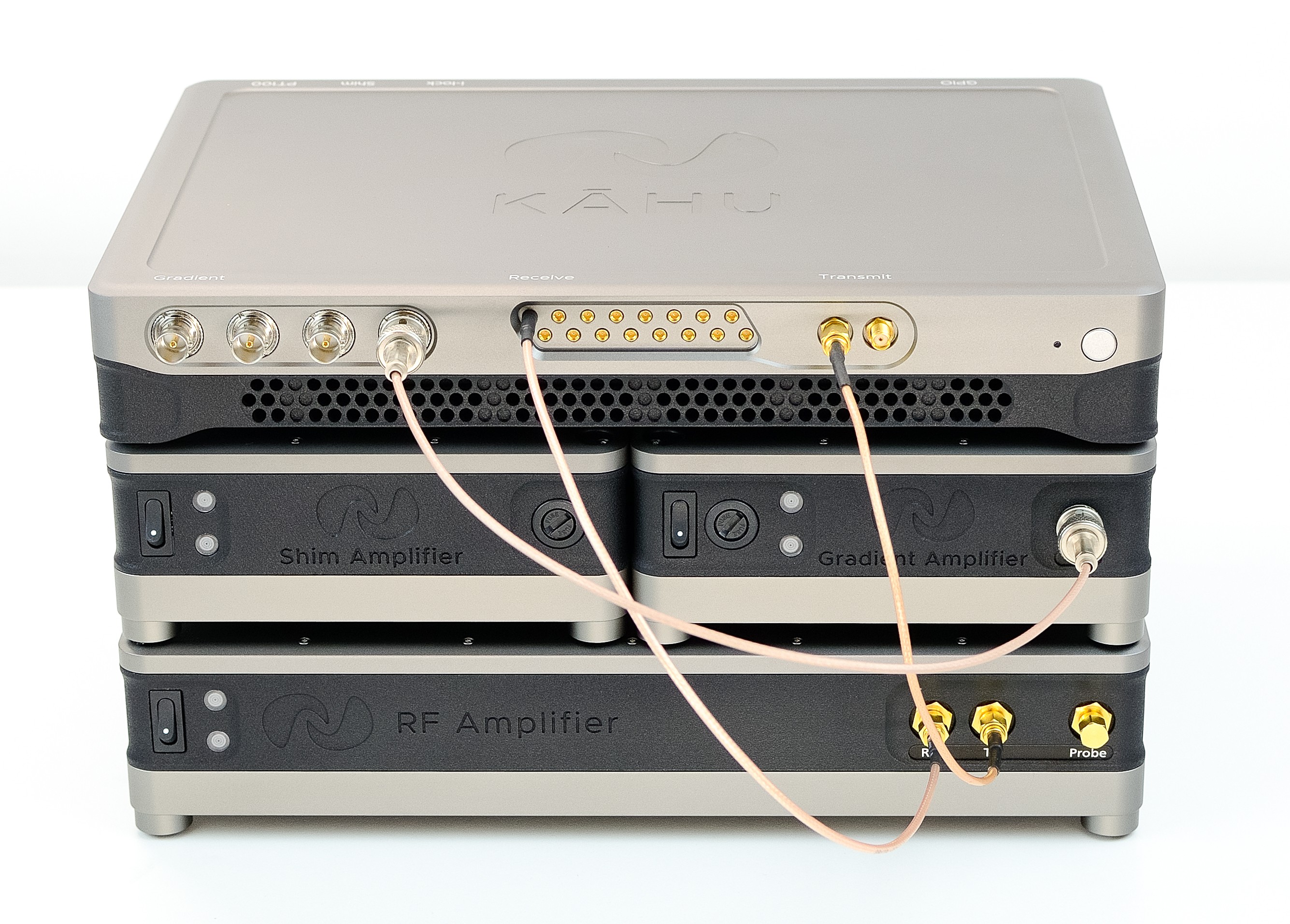
Begin by arranging the modules as shown in the image below with the Kāhu Spectrometer placed on top of the drive module(s). Note that the image below also shows the Shim module in the stack-up. This module is not required to run the Gradient amplifier, and if it is not being used simply place the Gradient amplifier module to the side of Kāhu.
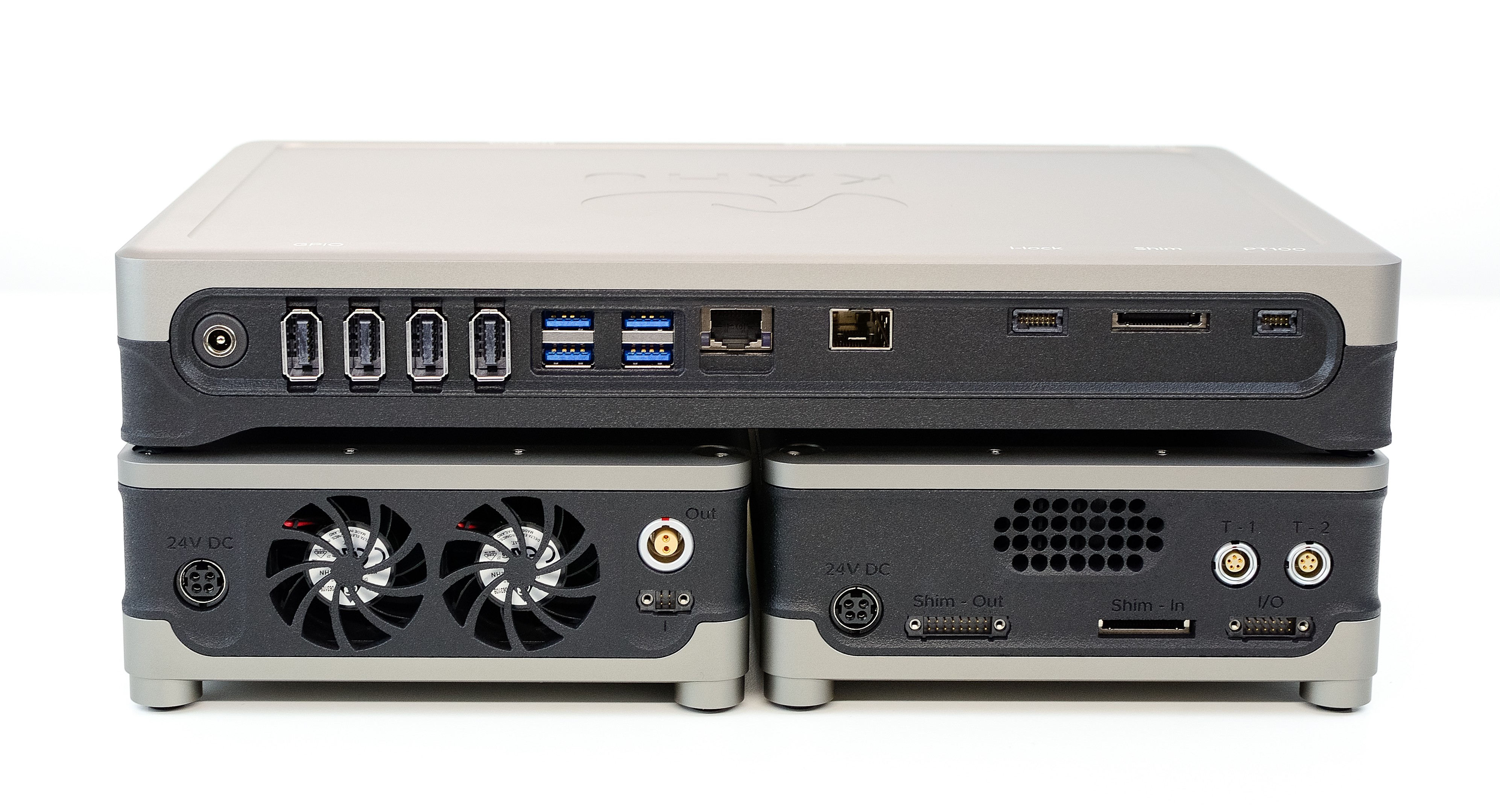
Kāhu, Shim & Gradient Amplifier modules stacked
Complete the initial rear Kāhu connections as explained in the Kāhu Hardware Connections section. Connect the 24V, 160 W external power brick to the Gradient amplifier (do not turn amplifier on).
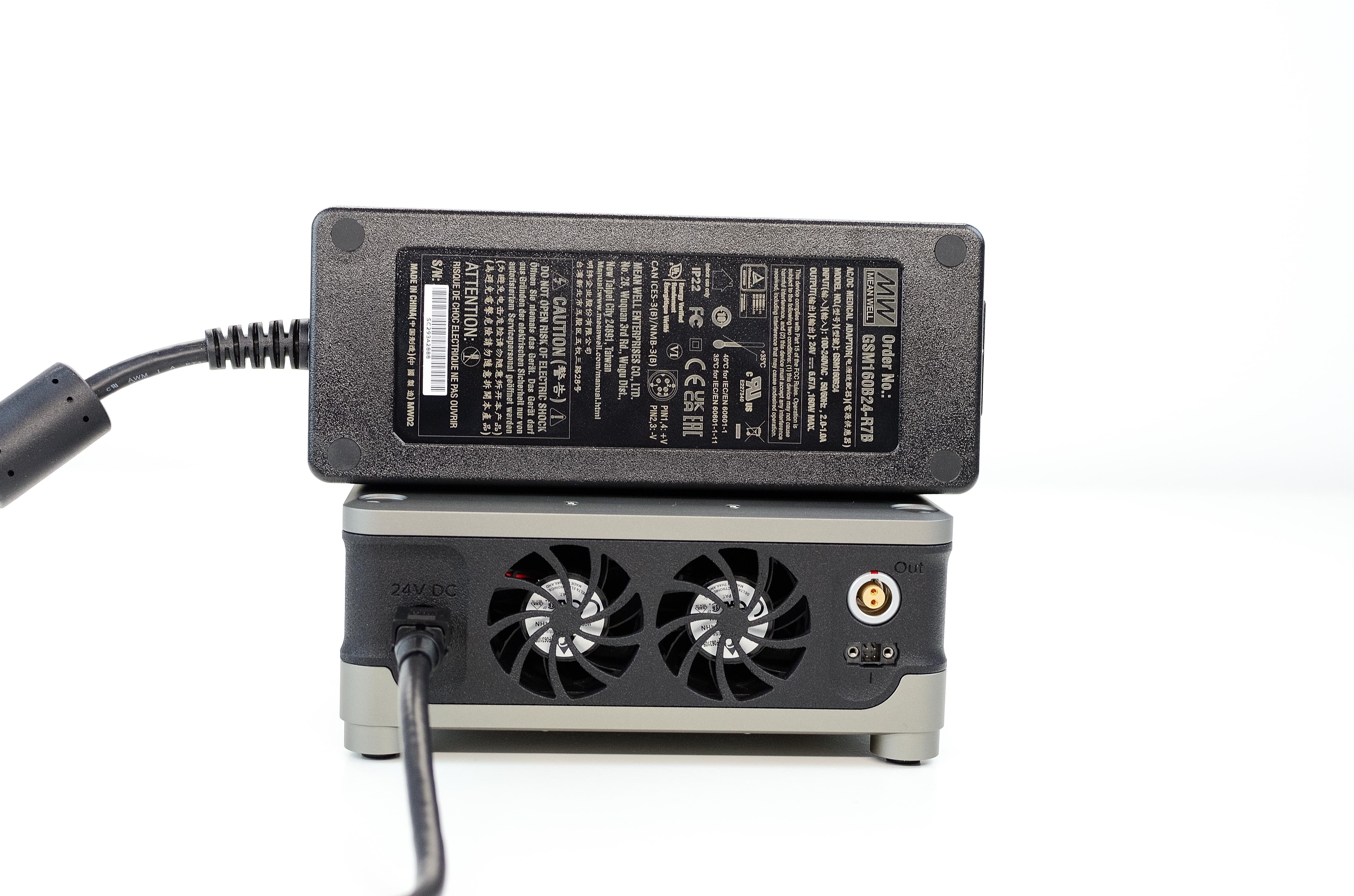
Power supply: 24V, 160W
Next, using the provided cable, fasten the 4-pin interlock connector to the ‘I’ port on the amplifier module using the H2.0 driver tool provided. Take care not to overtighten. Connect the other end of the cable to the i-lock port on Kāhu.
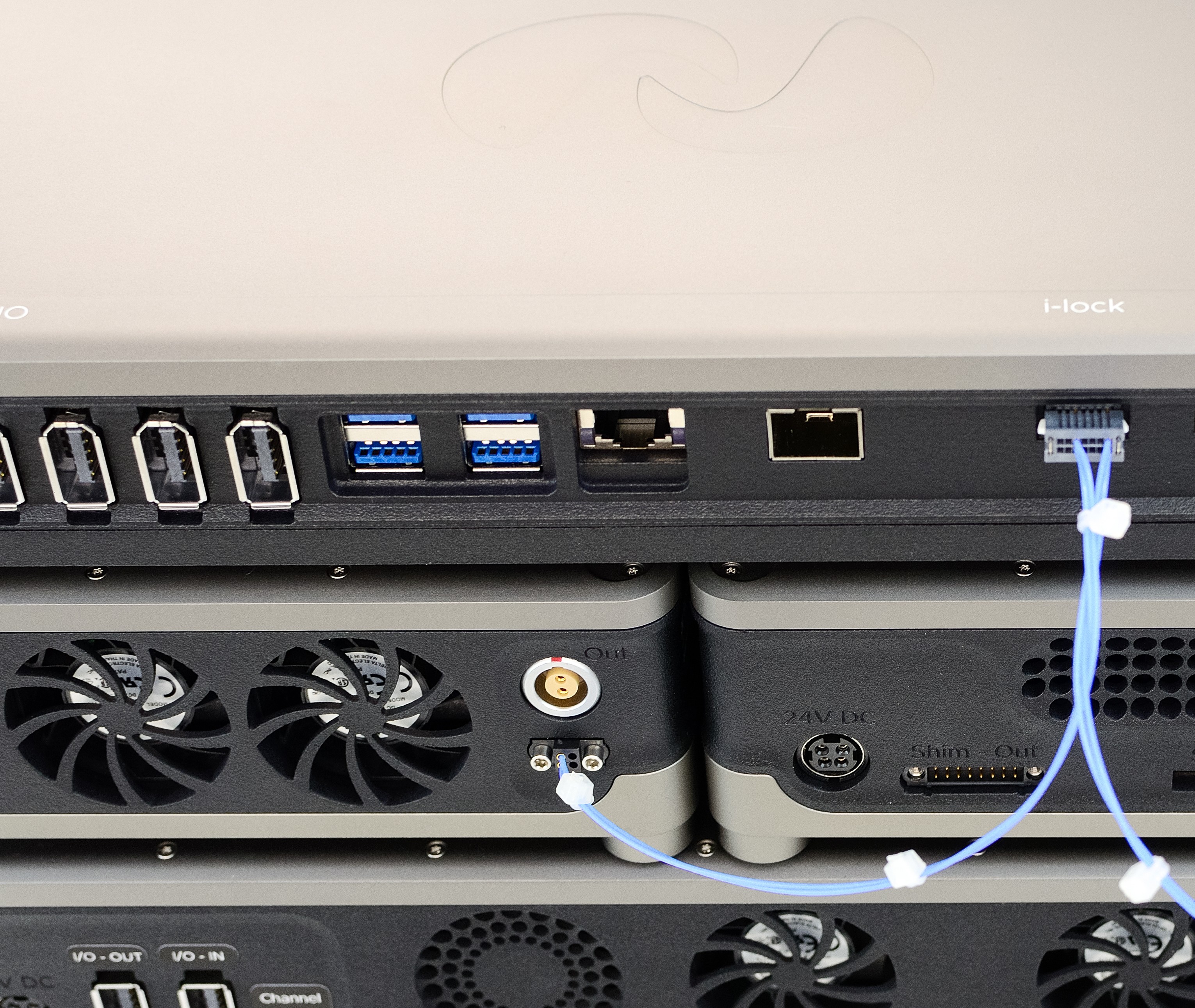
Interlock cable connection
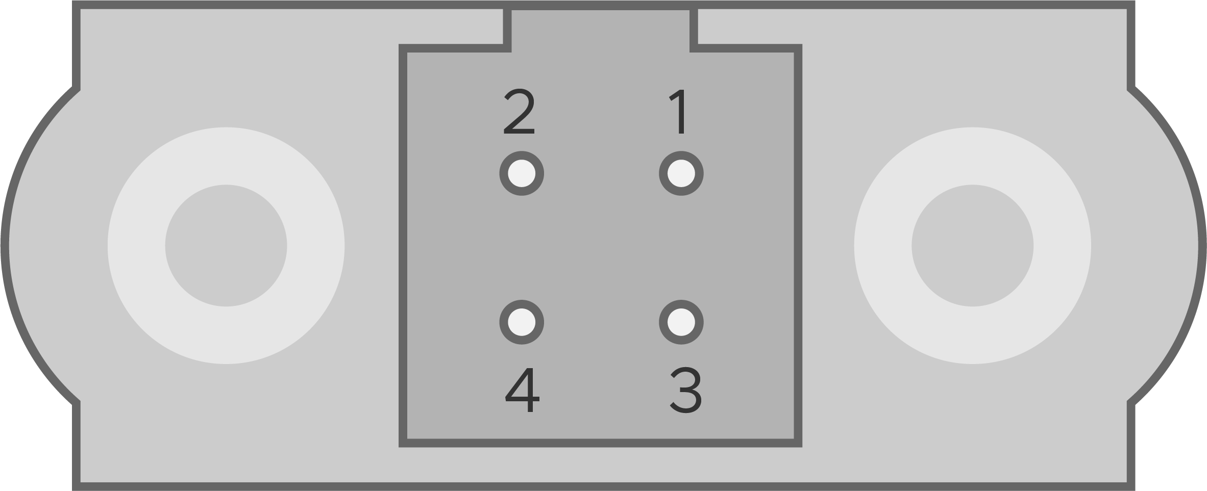
Lastly, connect the high power gradient output port (labelled Out on the module) to your gradient coil. The mating connector required is the MMI-M1PG02S72 and the pinout on the module is as follows:
Pin No. |
Description |
|---|---|
1 |
I+ |
2 |
I- |
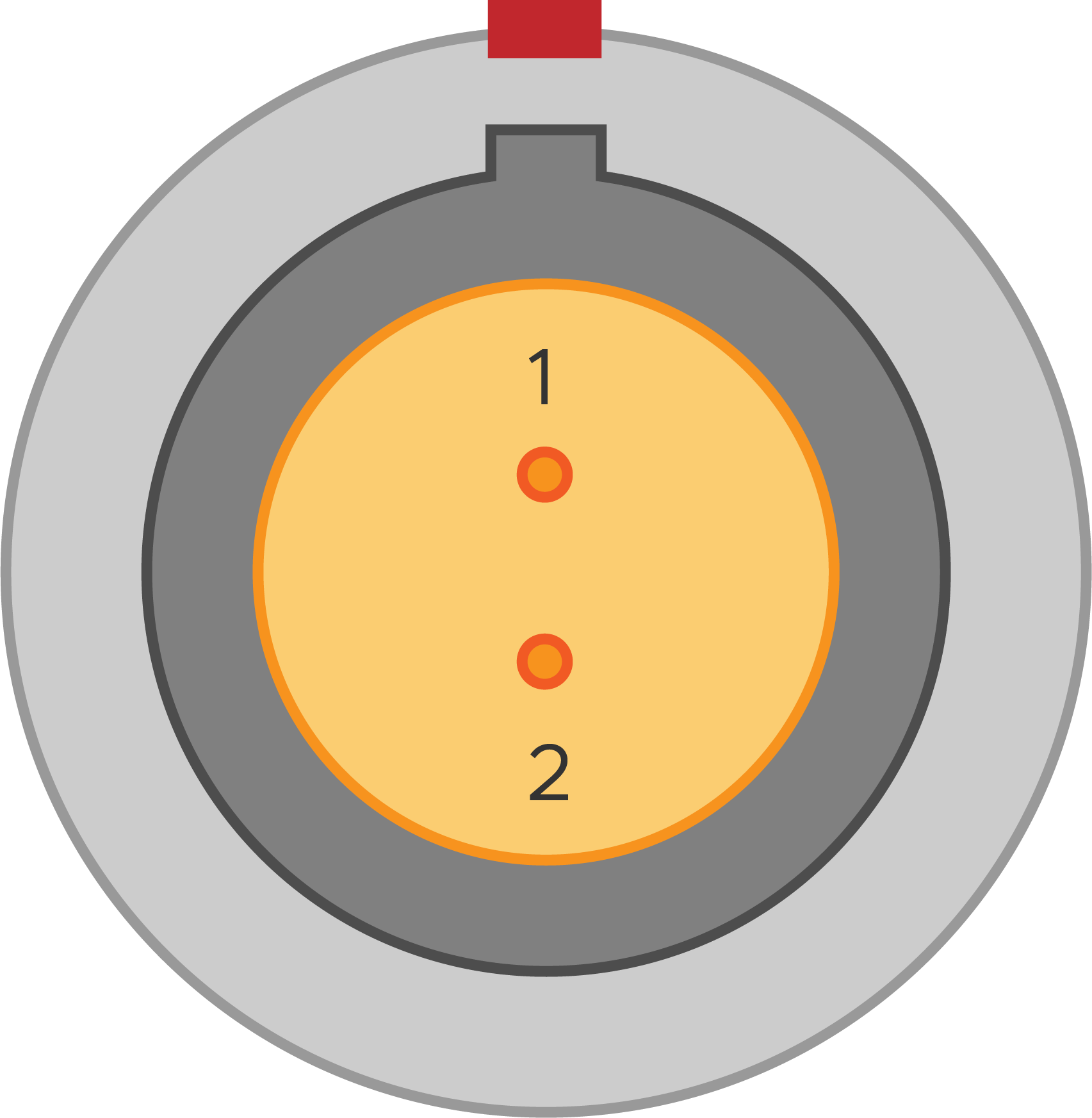
High power gradient output pinout
Note
To avoid damage, take care to correctly orientate the connector by aligning the red markings on the connector and port.
Step 2 - Front Cable Connections
Connect a gradient control output from Kāhu to the low power gradient input BNC connector on the Gradient Amplifier module. The example below shows Gradient port 3 from Kāhu connected to the module.
Low power gradient connection
Step 3 - Power up
Power on Kāhu and establish a network connection from your PC. Once Kāhu power up has finished, you can power on the Gradient Amplifier with the power switch.
Specifications
General
Power Supply |
24 V, 160 W |
Dimensions |
150 x 200 x 65 mm (Width x Depth x Height) |
Weight |
2 kg |
Amplifier
Current output Range |
±10 A |
Voltage output Range |
±15 V |
Input Voltage Range |
±10 V |
Load Resistance |
0.5 - 1 Ω, 1 Ω Nominal |
Transconductance Gain |
1.0 A/V |
Maximum Overall Duty Cycle (±10 A output) |
|
Maximum Continuous Pulse Width (±10 A output) |
10 seconds [1] |
Detailed Description
Amplifier
The amplifier is a voltage controlled current source design. The output current will be proportional to the input voltage according to the following transfer function:
Interlock
The interlock is a 5 V TTL input, which is used to enable the amplifier module when a pulse sequence is active, and disable it when in standby. The part number for the mating connector used in the interlock cable (on the amplifier side) is the M80-4140498. The pinout of the ‘I’ port on the module is:
Pin No. |
Description |
|---|---|
1, 2, 3 |
GND |
4 |
Interlock input |
Interlock port pinout
Errors
If the red indicator light turns on, the system has exceeded the temperature cutoff threshold. While the red indicator is on the amplifier will be disabled. The amplifier will re-enable automatically once it has cooled down. If the error light turns on you should:
Wait for the light to turn off before attempting to use the amplifier again
Reduce your gradient pulse duty cycle (e.g. increase repetition time)
Then, if the problem persists:
Check that the fans are still functional, you should hear them running as soon as the system is powered on
Ensure that the dust filters aren’t clogged (see Maintenance)
Maintenance
To ensure the module doesn’t begin to overheat, the dust filter should be cleaned regularly. To access the filter, ensure the module is powered off then remove the 4 screws on the panel on the under side of the module as seen below. The filters can then be removed, cleaned, and refitted.
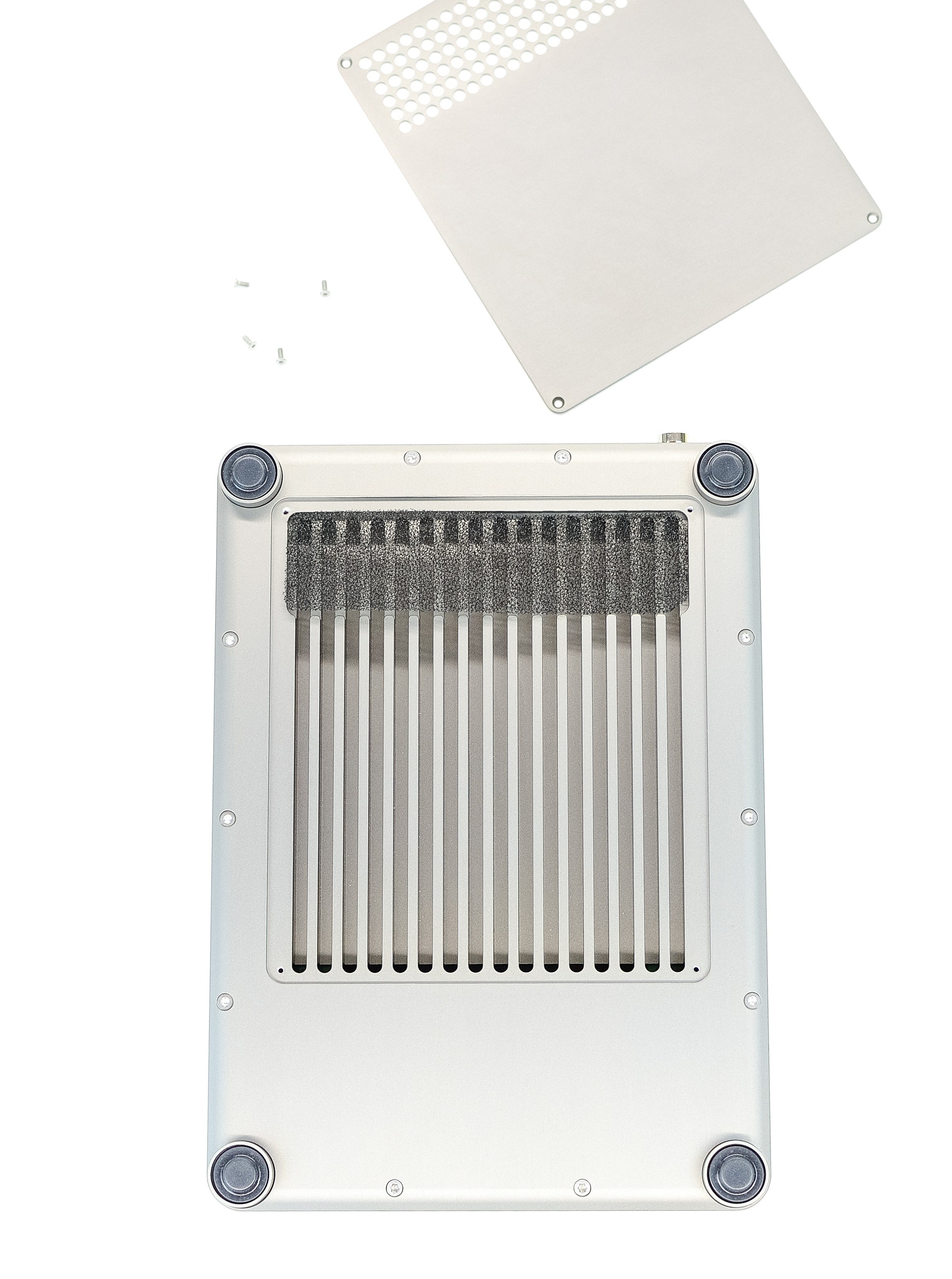
Dust filter cover removed
Note
Ensure filters and panels are refitted before the module is powered back on.