RF Amplifier Module
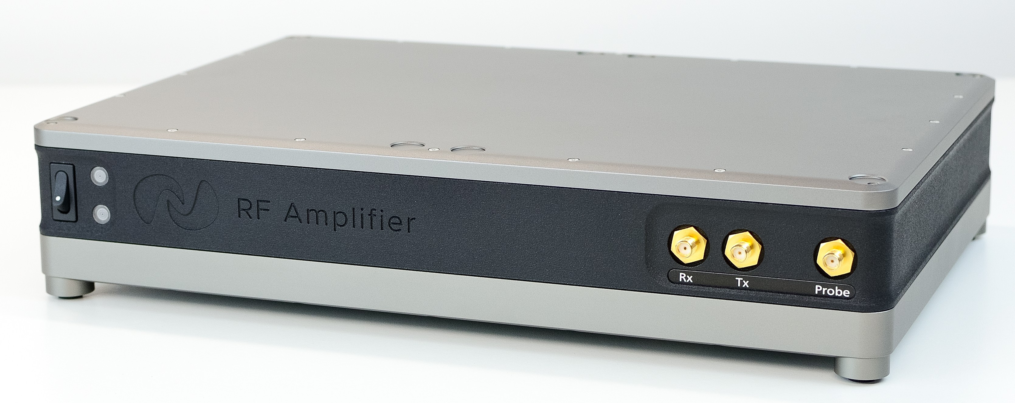
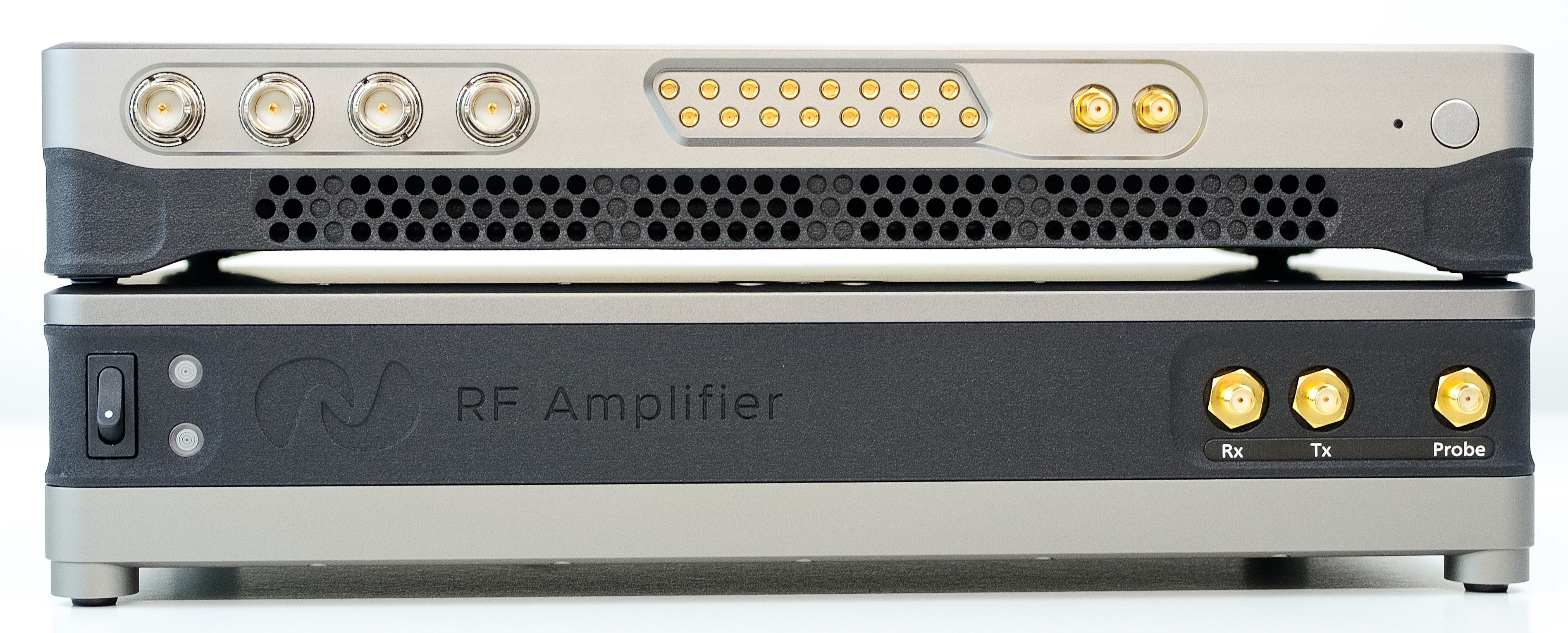
RF Amplifier Module Front
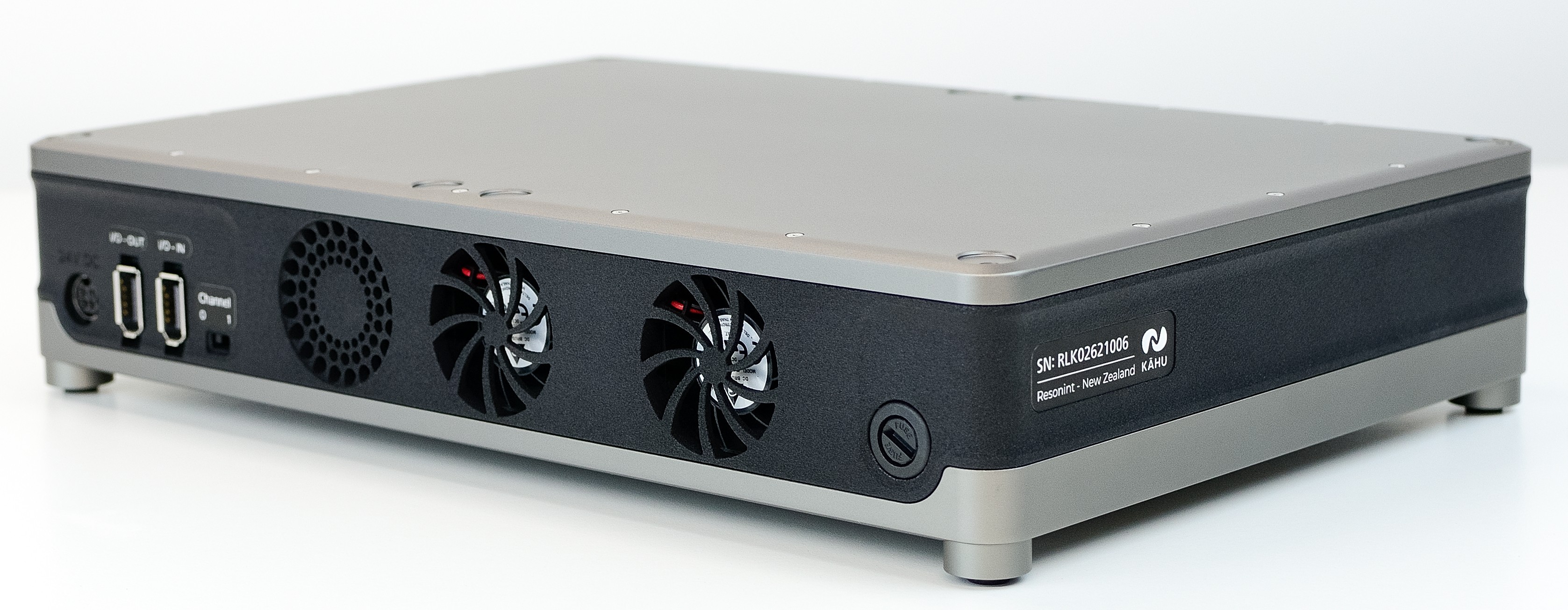
RF Amplifier Module Rear
This module enables you to connect a Transmit/Receive MR probe to Kāhu, amplifying the transmitted and received signals.
Features:
50 W RF power amplifier for transmit
30 to 75 dB programmable gain preamplifier for receive
Active Transmit/Receive switch with swappable quarter-wave line
Connections
On front of the module you will find the SMA connectors for attaching the Rx and Tx ports from Kāhu, as well as a port to connect your Probe to. Additionally you will find the on/off power switch and the indicator lights. The top light will illuminate green when the module is powered on, while the bottom light will flash blue when the RF amplifier is transmitting an RF pulse or will show red to indicate an over-duty-cycle or over-temperature error. During short RF pulses it may be difficult to see the blue light.
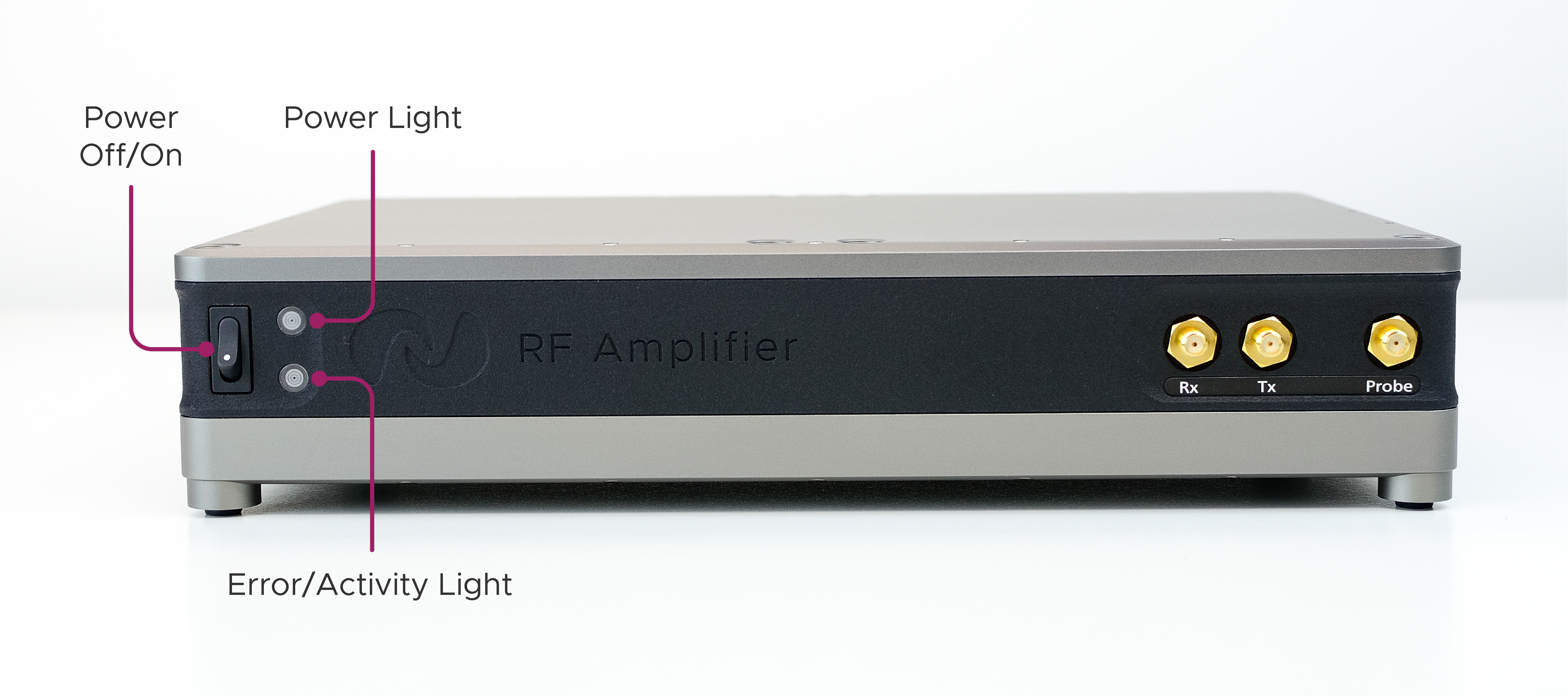
Front Controls & Indicators
The power-in port, I/O ports and Tx channel selection switch can be found on the back of the module.
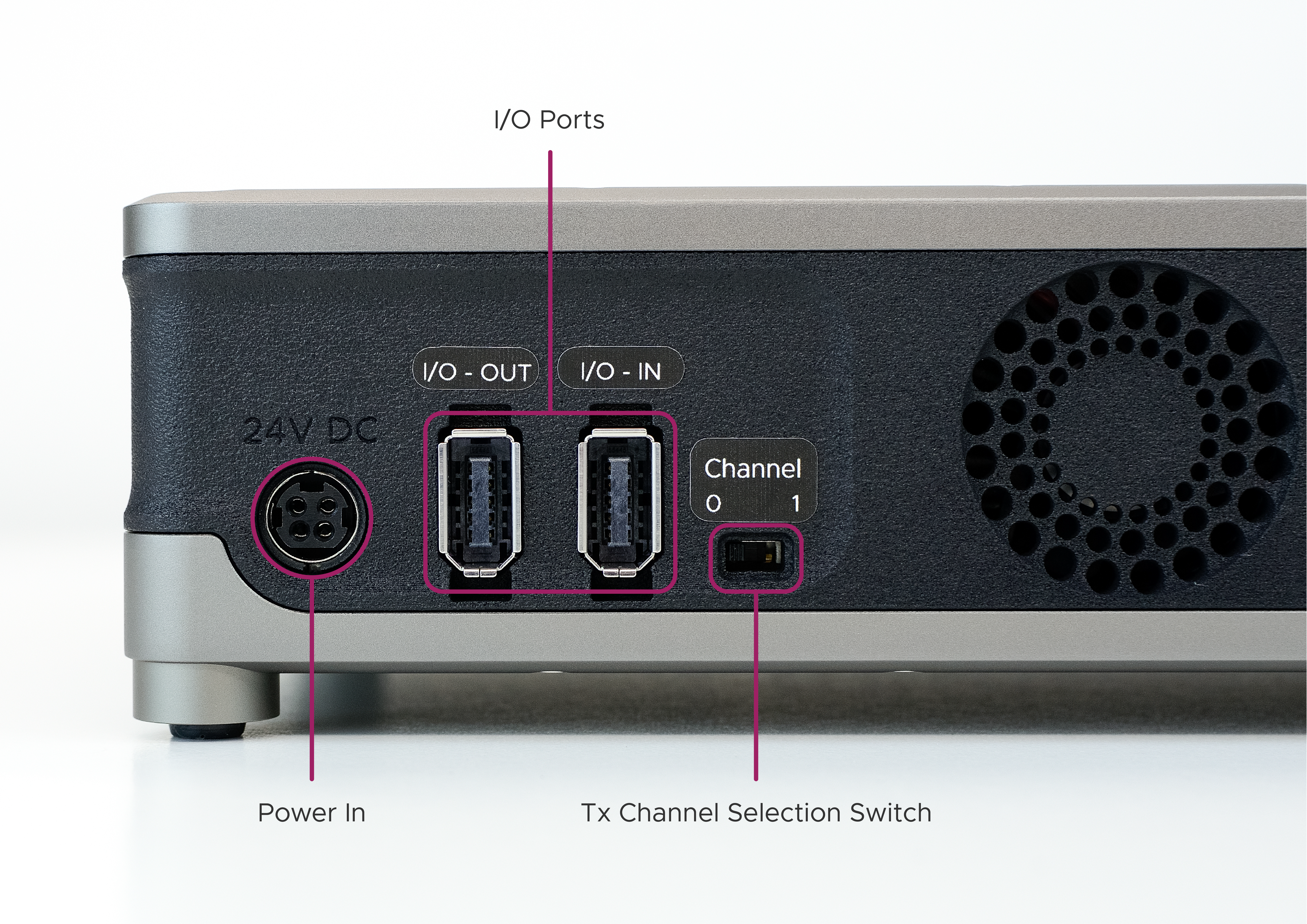
Rear Ports & Gating Channel Switch
On the underside of the module there are three removable panels. Two of these are cooling grilles which provide access to the dust filters when removed. The filters should be cleaned when dust has accumulated to ensure adequate airflow. The other panel may be removed in order to change the quarter wave line module.
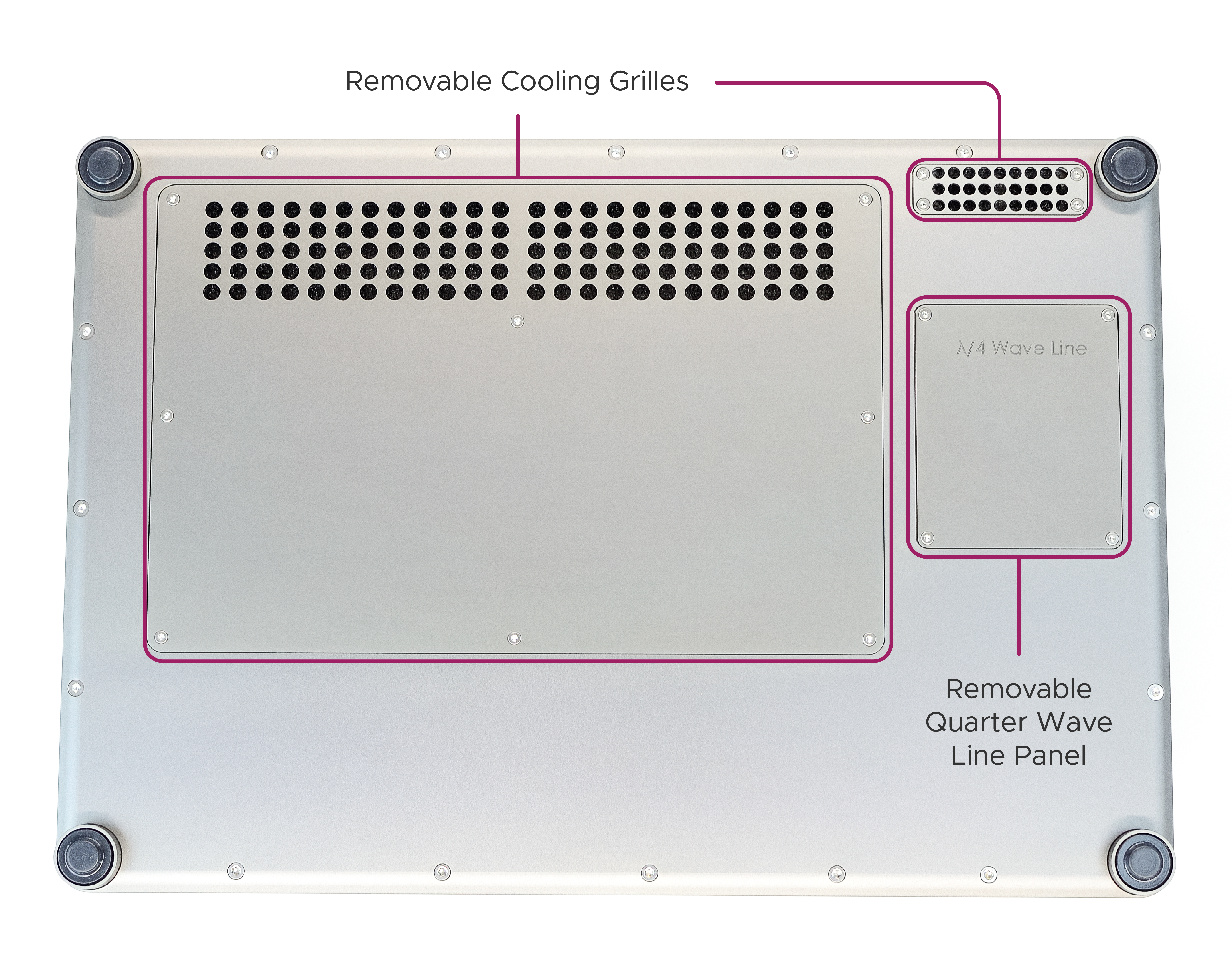
Underside Removable Panels
Setup Guide
This section will guide you through the steps required to set up the 50 W RF Amplifier Module with the Kāhu Spectrometer.
Warning
Ensure the Amplifier module is powered OFF during Kāhu power up and shutdown, and while changing RF or IO connections.
Step 1 - Quarter Wave Line
Ensure your amplifier is tuned to the target frequency by fitting the correct quarter-wave line module. To learn how to change the quarter-wave line module, see the How to retune the 50W RF Amplifier section.
Step 2 - Rear Cable Connections
Arrange the modules as shown in the image below with the Kāhu Spectrometer placed on top of the drive module(s).
Kāhu & RF Amplifier module stacked
Complete the initial rear Kāhu connections as explained in the Connections section. Connect the 24V, 120 W external power brick to the amplifier and connect GPIO port 0 of Kāhu to the I/O IN port of the amplifier. Ensure the Channel switch is set to 0.
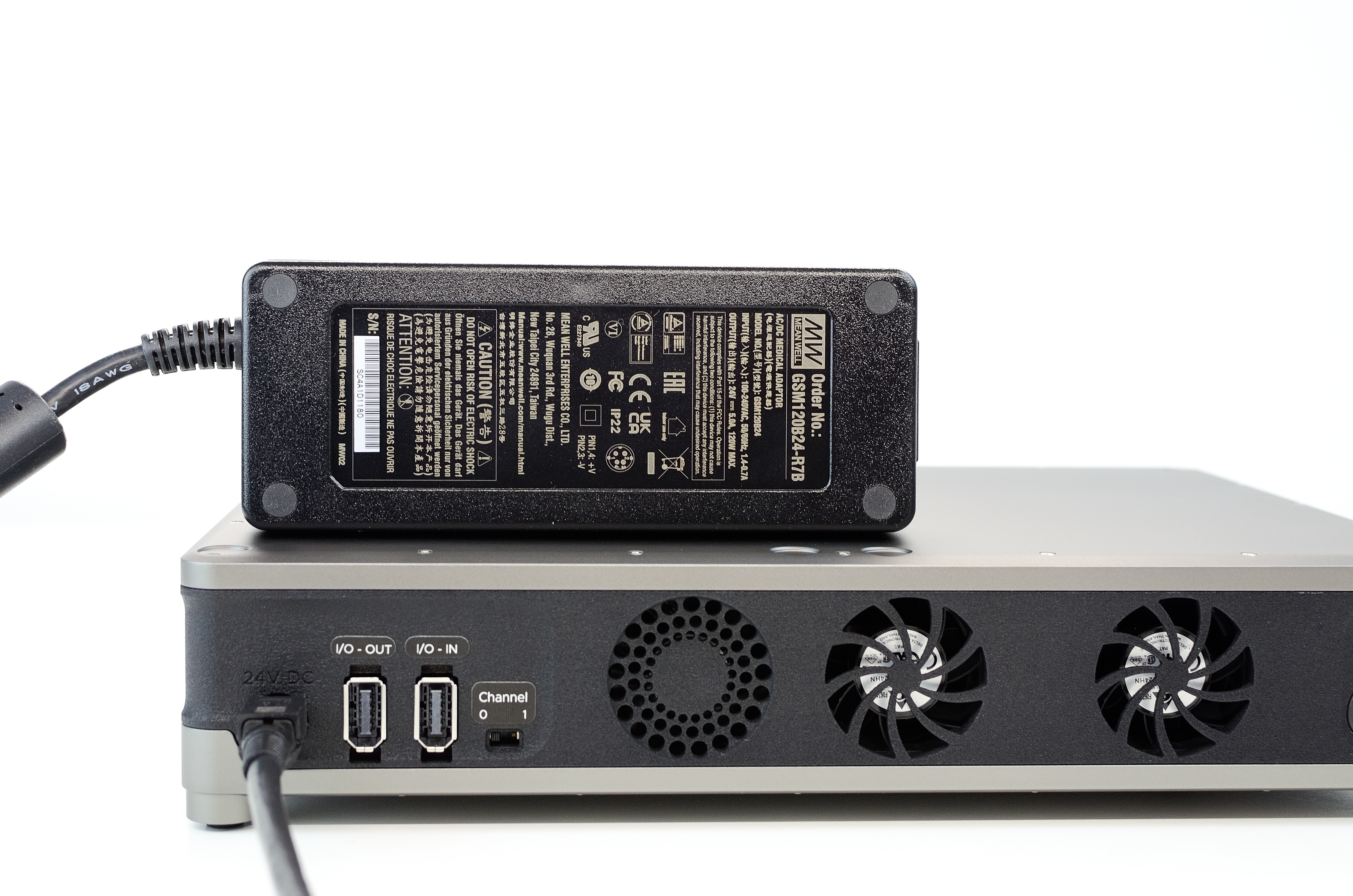
Power supply: 24V, 120W
IO connection for digital receive gain and T/R switch control
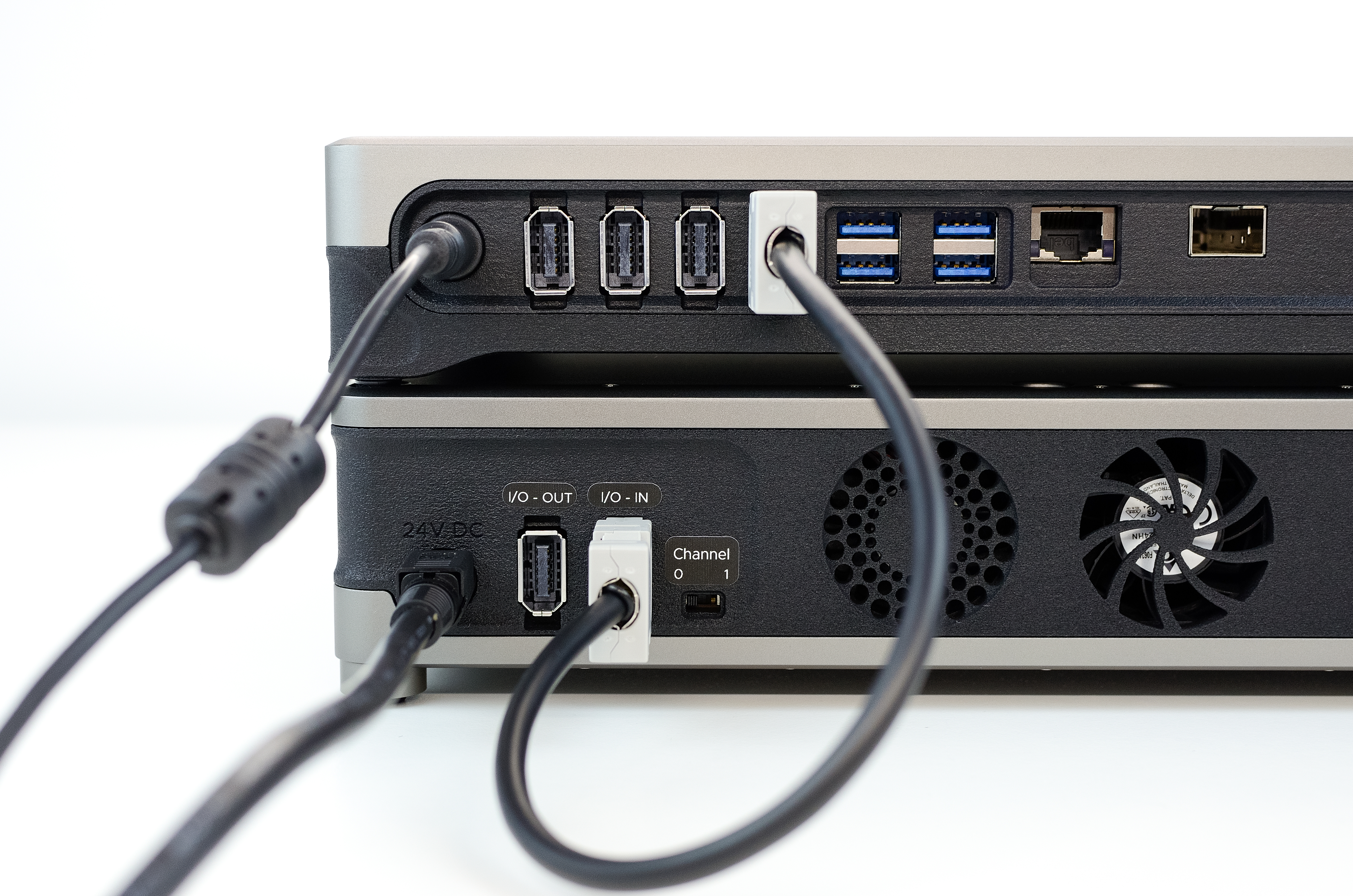
If you are using two RF amplifier modules, then connect the I/O OUT port from the first module to the I/O in port of the second module so that they are daisy-chained together. Set the Channel switch of the second module to 1. The second amplifier module will also require a power supply. An example of this is shown below.
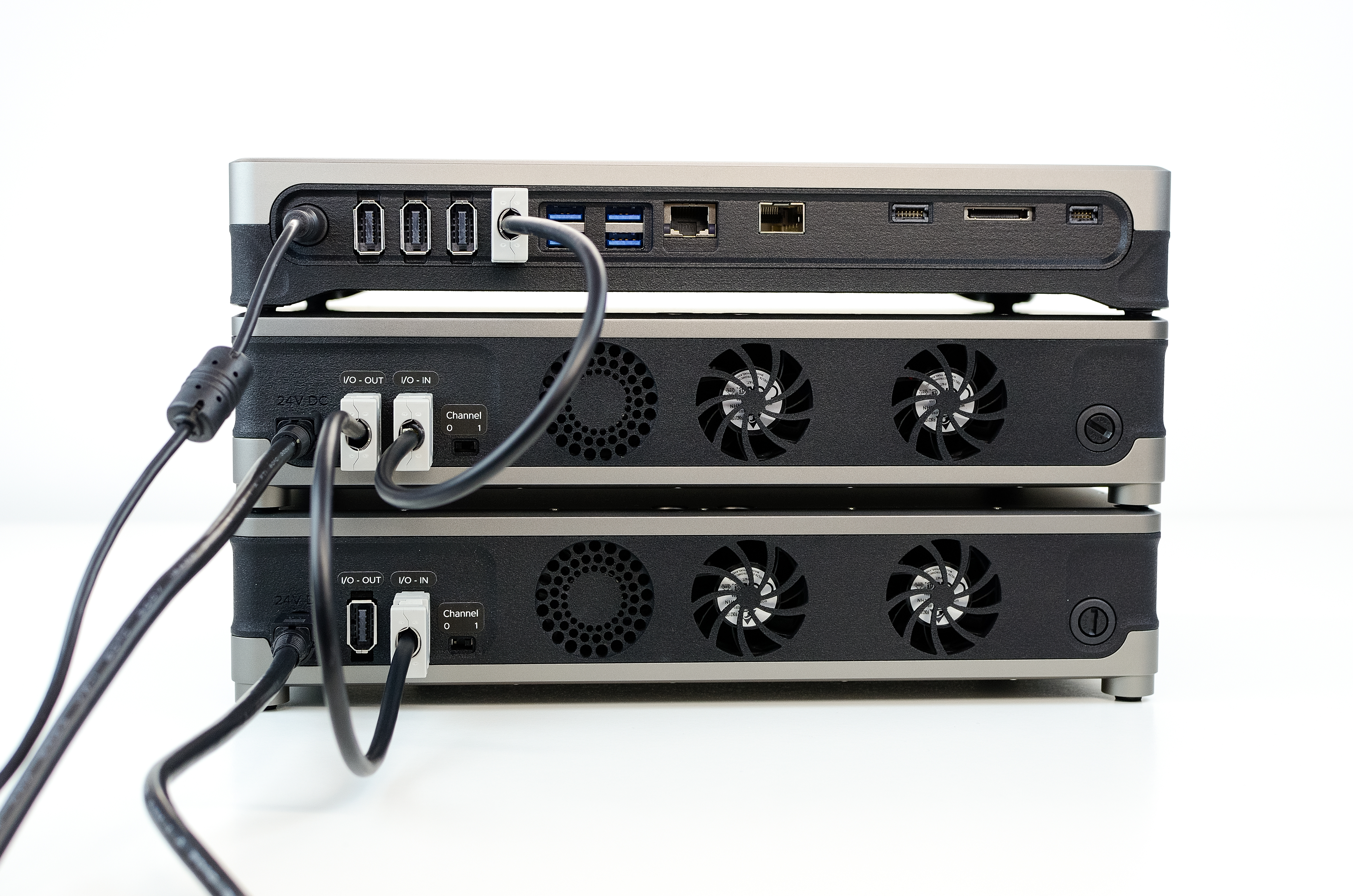
Daisy-chained IO connection with two amplifier modules
Step 3 - Front Cable Connections
All front cable connections are made with an RF coaxial cable. Make the following connections:
Connect Kāhu Tx channel 0 port to the Tx port on the RF amplifier module.
If you are using a second amplifier module, connect Kāhu Tx channel 1 port to the Tx port of the second module.
connect an Rx port from Kāhu to the Rx port on the amplifier
connect the Probe port from the amplifier to your probe
Note
For correct connectivity, ensure the Tx channel from Kāhu matches the position of the Channel switch on the amplifier
Step 4 - Power up
Power on Kāhu and establish a network connection to your PC. Once connected and Kāhu has finished booting up, you can power on the RF amplifier with the power switch.
Specifications
General
Power Supply |
24 V, 120 W |
Dimensions |
300 x 200 x 65 mm (Width x Depth x Height) |
Weight |
3.5 kg |
Technical
Tx Power |
50 W RMS |
Tx Gain |
37 dB [1] |
Frequency Range |
10 - 150 Mhz |
T/R switching delay |
2 μs |
Tx/Rx/Probe Connector |
SMA |
Rx Preamp Gain |
30 - 75 dB digitally adjustable. |
Detailed Description
Error Indicator
There are two possible causes for the error indicator to light up. An over-duty fault or an over-temperature fault. If the red error light turns on you should:
Wait for the light to turn off before running any other sequences
Reduce the duty cycle of your RF pulses
Check that the fans are still functional, you should hear them running
Ensure that the dust filters are not clogged (see Maintenance)
How to retune the 50W RF Amplifier
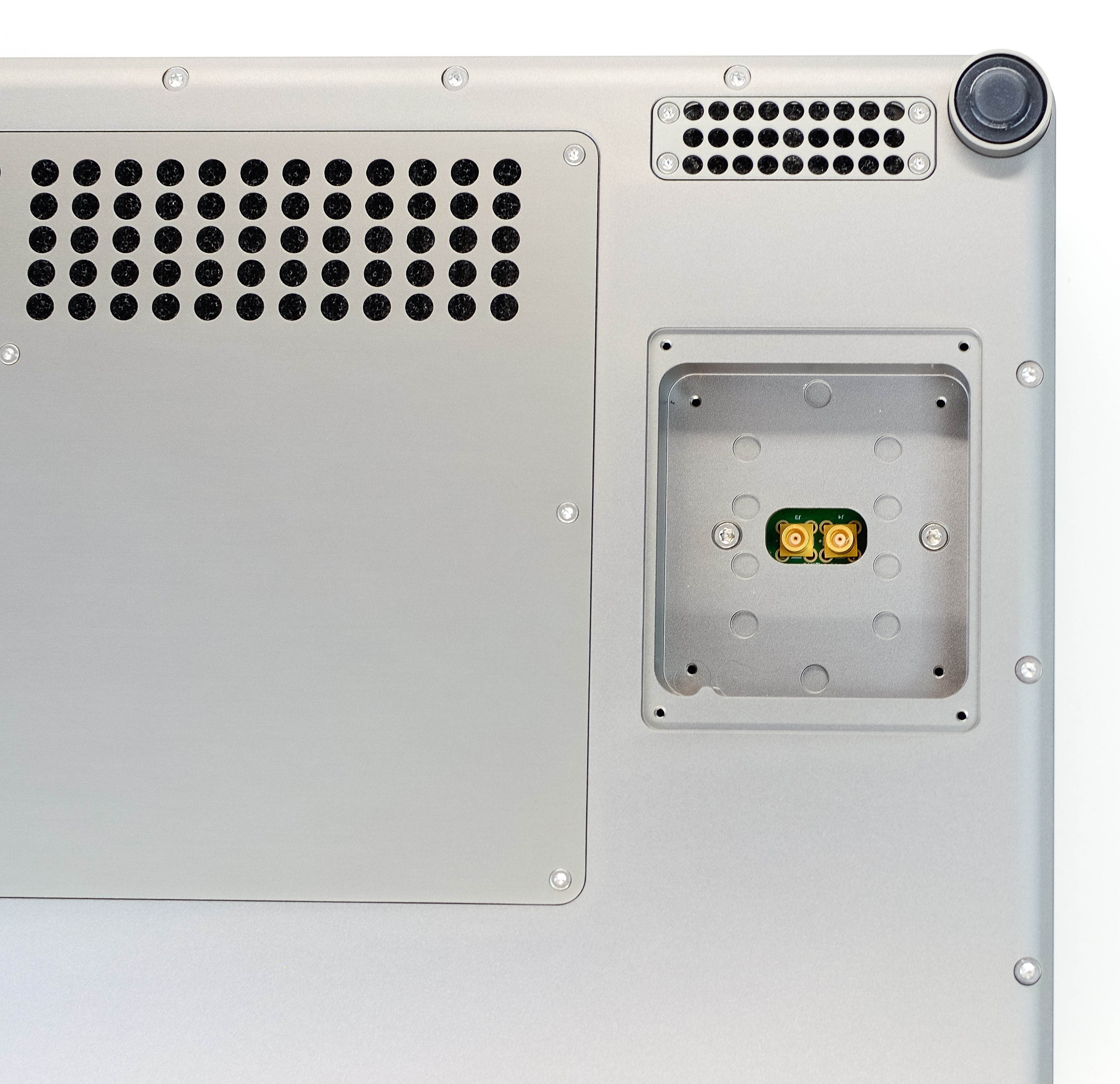
The 50 W RF Amplifier module can be retuned by swapping the quarter-wave line module. To remove the fitted module, first remove the quarter-wave line panel (found on the underside of the amplifier module) by unscrewing the 4 visible screws. Once removed, you will have access to the quarter-wave line module. Unscrew the 4 phillips screws that are holding the module in place.
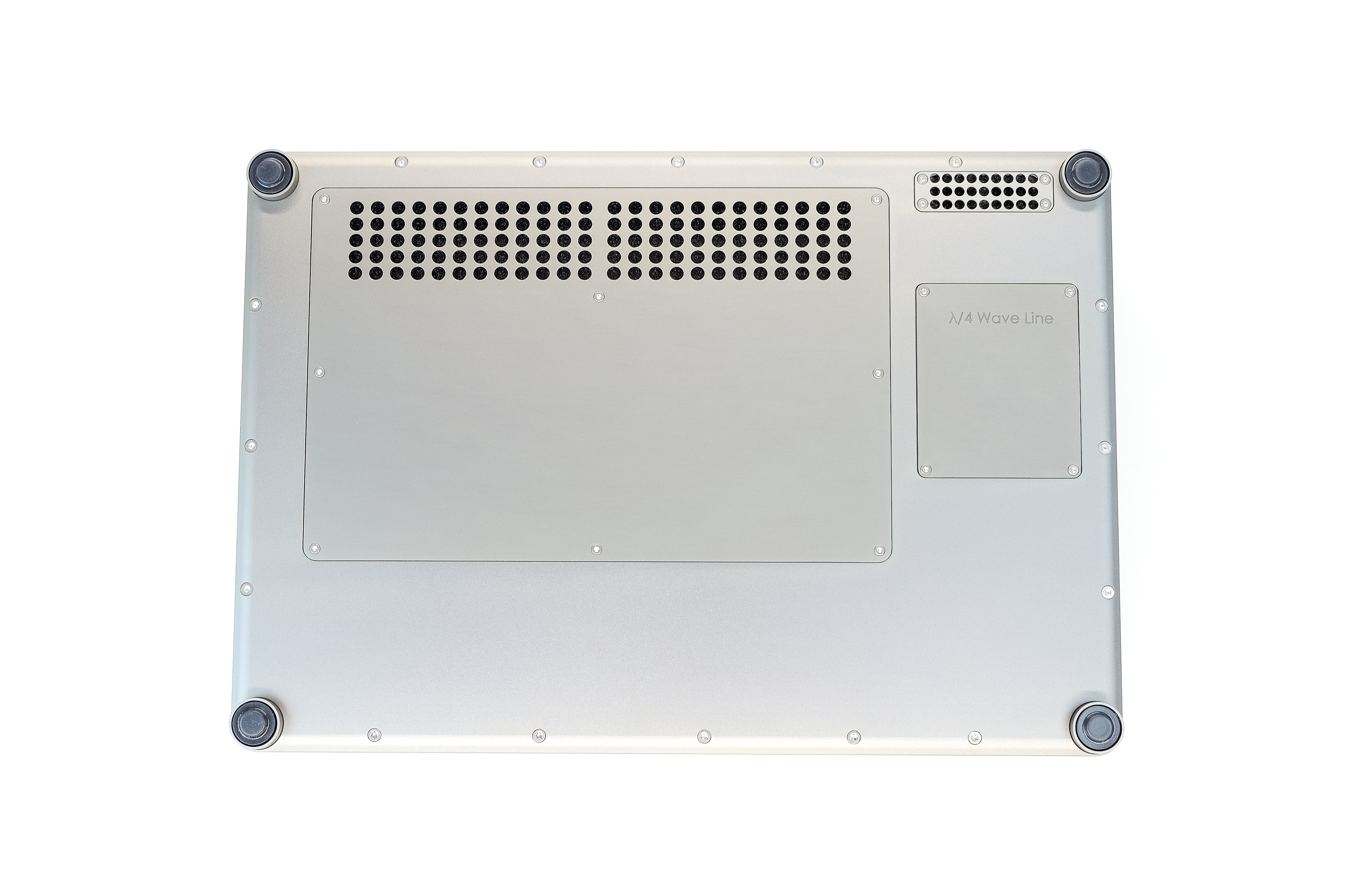
RF Amplifier underside
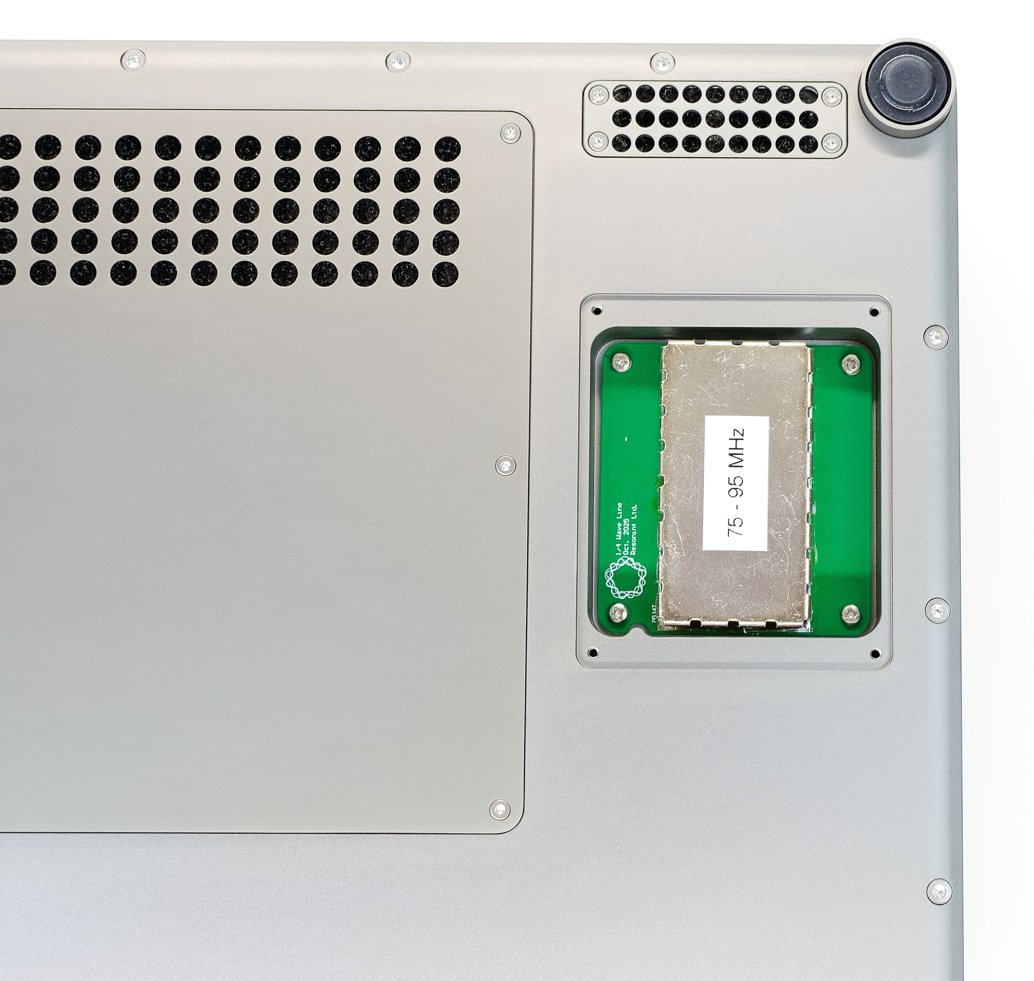
Quarter-wave cover removed
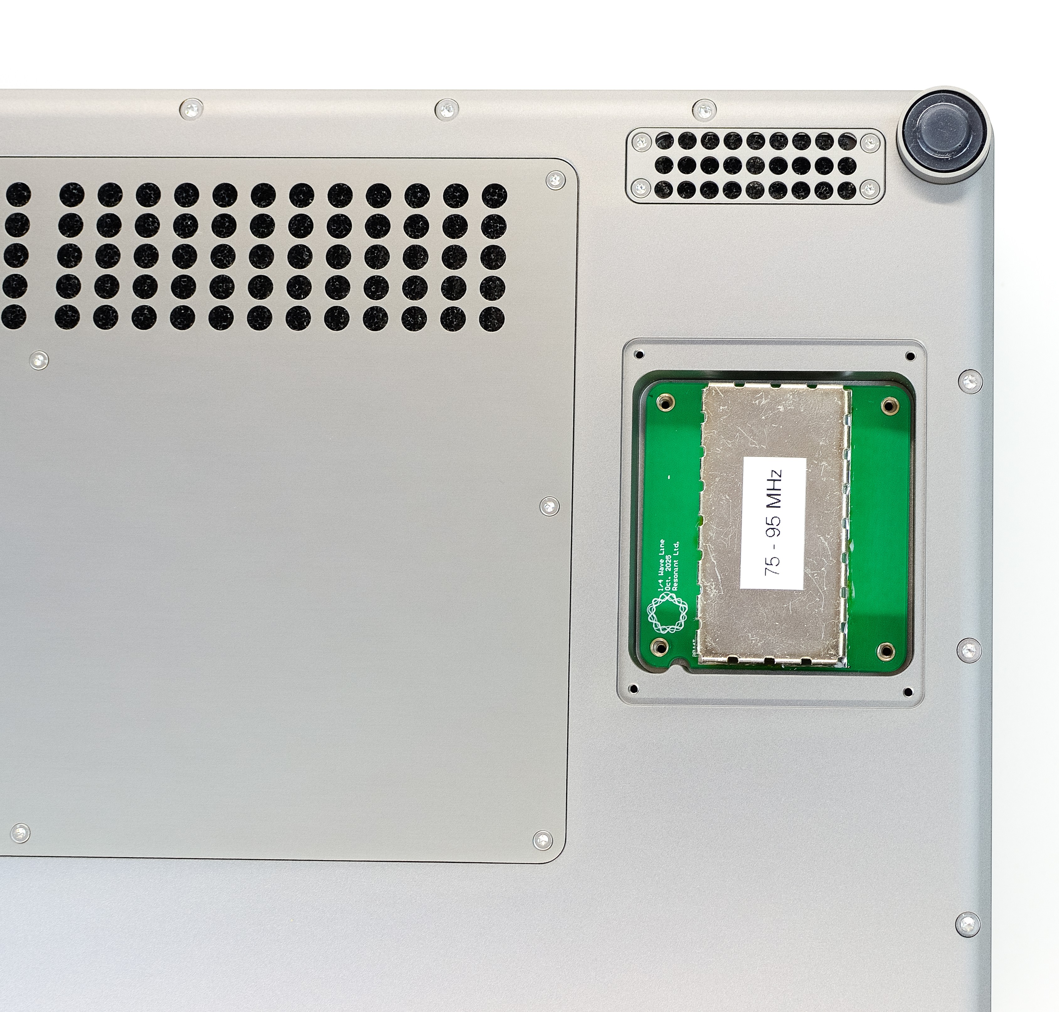
Screws removed
Carefully pull the module out to disconnect it from the amplifier.
Quarter-wave module removed
Insert the alternative quarter-wave line module, taking care to correctly align the notch on the bottom left. Press to click it into place and fasten the 4 phillips screws to secure it. Finish by refitting the panel.
Maintenance
To ensure the module doesn’t begin to overheat, the dust filters should be cleaned regularly. To access the filters, ensure the module is powered off then remove all screws on each of the cooling grilles as seen below. The filters can then be removed, cleaned, and refitted.
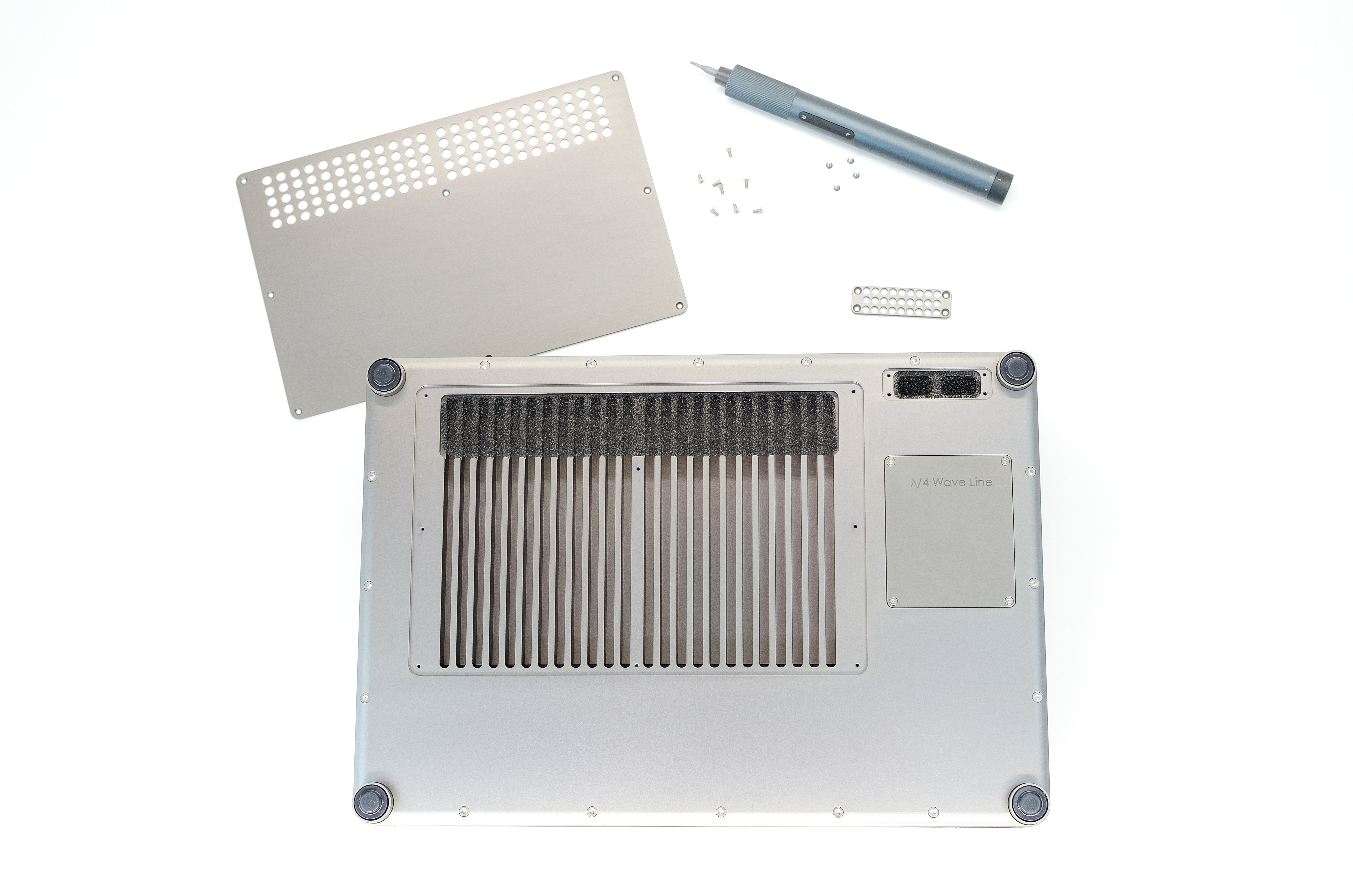
Dust filter covers removed
Note
Ensure filters and panels are refitted before the module is powered back on.