Kāhu Spectrometer
The Kāhu spectrometer is a multi-channel MR console with integrated gradient and shim controllers. The base model includes 2 transmit channels and 4 receive channels, while the upgraded model provides 16 receive channels. The Kāhu QuickStart Guide explains the basics of how to set up the console.
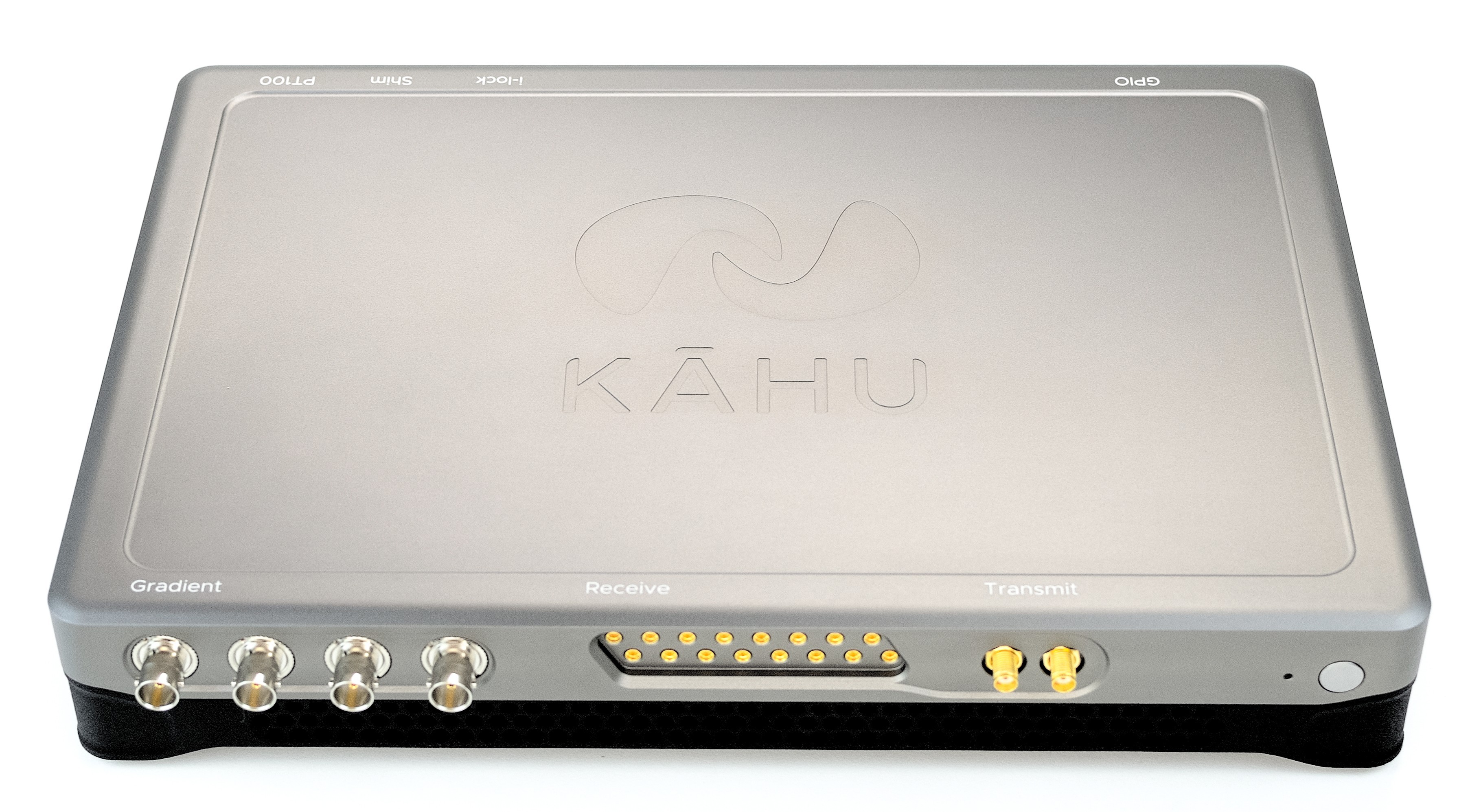
Kāhu spectrometer, 16 channel model
Specifications
Unless stated otherwise, these specifications apply to both the base and 16 channel models of Kāhu.
General
Power Supply |
24 V, 90 W |
Dimensions |
300 x 200 x 60 mm (Width x Depth x Height) |
Weight |
1.8 Kg |
RF Transmit
Channels |
2 |
Frequency Range |
100 kHz - 140 MHz |
DAC Sample Rate |
400 MSPS |
Resolution |
16-bit |
Output Power |
0 dBm (0.63 Vpp) |
Output Impedance |
50 Ω |
Output Coupling |
AC coupled |
Connector |
SMA |
RF Receive
Base Model |
16 Channel Model |
|
|---|---|---|
Channels |
4 |
16 |
Receive Processor |
FPGA-based 32-bit quadrature |
FPGA-based 32-bit quadrature |
Frequency Range |
100 kHz - 140 MHz [1] |
100 kHz - 140 MHz [1] |
Crosstalk, worst neighbor |
-80 dB |
-70 dB [2] |
Sample Rate |
100 MSPS |
50 MSPS |
Resolution |
16-bit |
14-bit |
Input Power Range |
10 dBm (2 Vpp) |
10 dBm (2 Vpp) |
Input Impedance |
50 Ω |
50 Ω |
Input Coupling |
AC |
AC |
Connector |
SMA |
MMCX |
Gradient Controller
Channels |
4 |
Resolution |
16-bit |
Sampling Rate |
200 kSPS |
Voltage Range |
±10 V |
Max Current Output |
10 mA |
Output Type |
Single ended |
Connector |
BNC |
Shim Controller
Channels |
16 |
Resolution |
16-bit |
Sampling Rate |
50 kSPS |
Voltage Range |
±5 V |
Max Current Output |
1 mA |
Output Type |
Single ended |
Connector |
High Speed I/O (Cable provided) |
Digital I/O
General Purpose/Pulse Progammable Outputs |
28 |
Pulse Progam Trigger Inputs |
4 |
General Purpose Inputs |
4 |
Temperature Control
Temperature sensor inputs |
2x PT100 inputs, with 24-bit ADC |
PID control outputs |
2x 5 V PWM outputs |
Embedded Platform
Main Processor |
Quad-core ARM Cortex-A53 |
Pulse Sequencer |
FPGA-based real-time streaming engine |
Operating System |
Linux |
Memory |
4 GB 64-bit DDR4 |
Ethernet |
1 Gbps |
USB |
4x USB 3 ports |
Other Features |
Real Time Clock |
Detailed Description
GPIO
The Kāhu console has 4 GPIO ports (see Connections). Each port interfaces with 3.3 V TTL logic and has 7 output pins, 2 input pins and 1 ground pin. Following the pin numbering on the mating connector, the pin configuration for all ports is:
Part No. |
|
|---|---|
Pin No. |
Function |
1, 2, 3, 4, 5, 6, 8 |
Output |
7, 9 |
Input |
10 |
GND |
Note
The metal shielding on the mating connector will need to be removed in order to access the solderable pins and see the printed pin numbering.
The image below shows the mating connector in GPIO port 3.
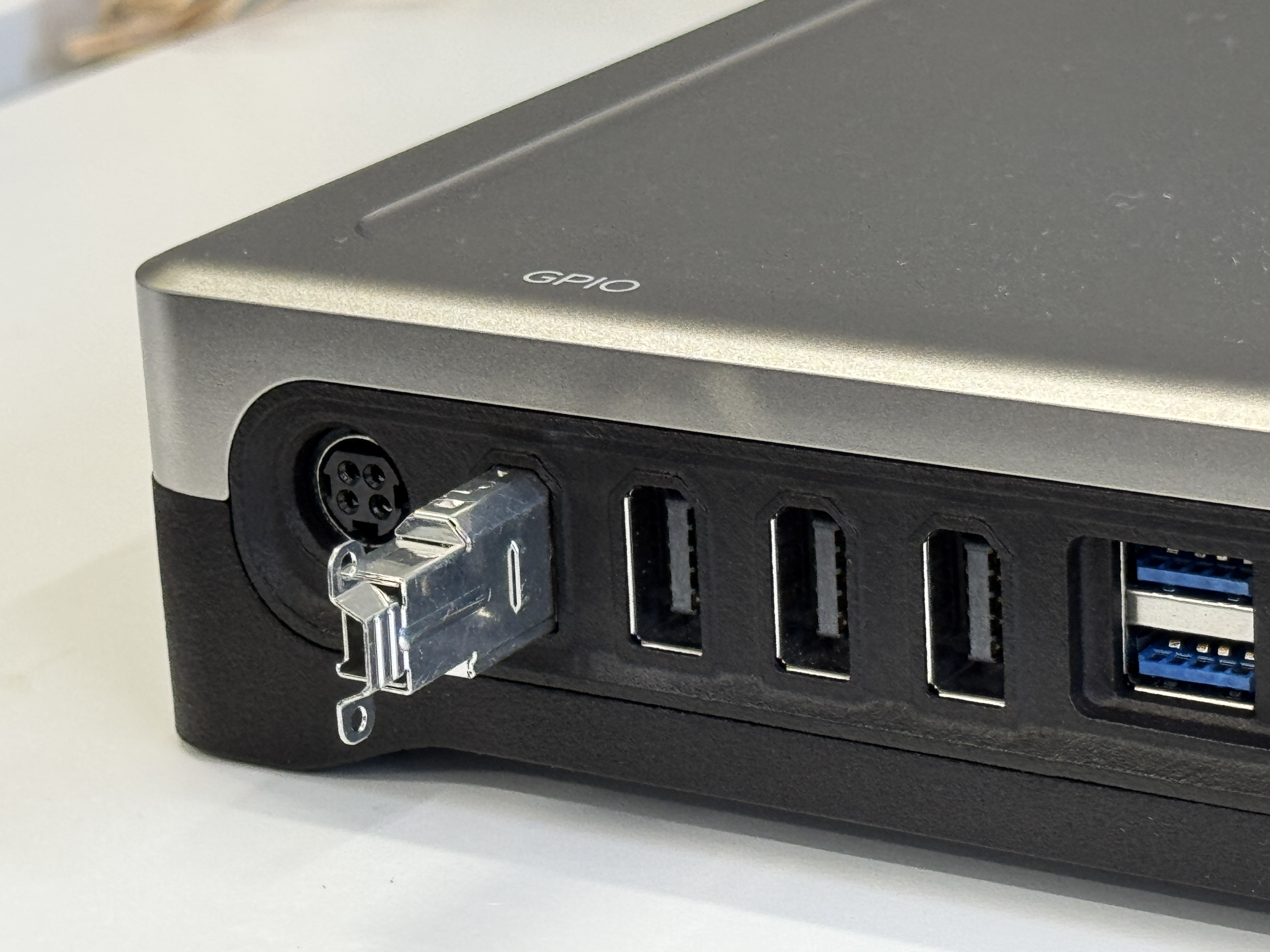
GPIO Connector
For information on controlling the GPIO pins see the General Purpose Outputs page.
Interlock
Kāhu has 5 interlock output pins available on the i-lock connector, 1 for the shims and 1 for each gradient channel. These can be used to enable amplifier modules when a pulse sequence is active, and disable them when in standby. The interlock pins are not directly controllable, they will automatically be brought high for the entire duration of a pulse sequence. They will be brought low when the pulse sequence finishes or is aborted.
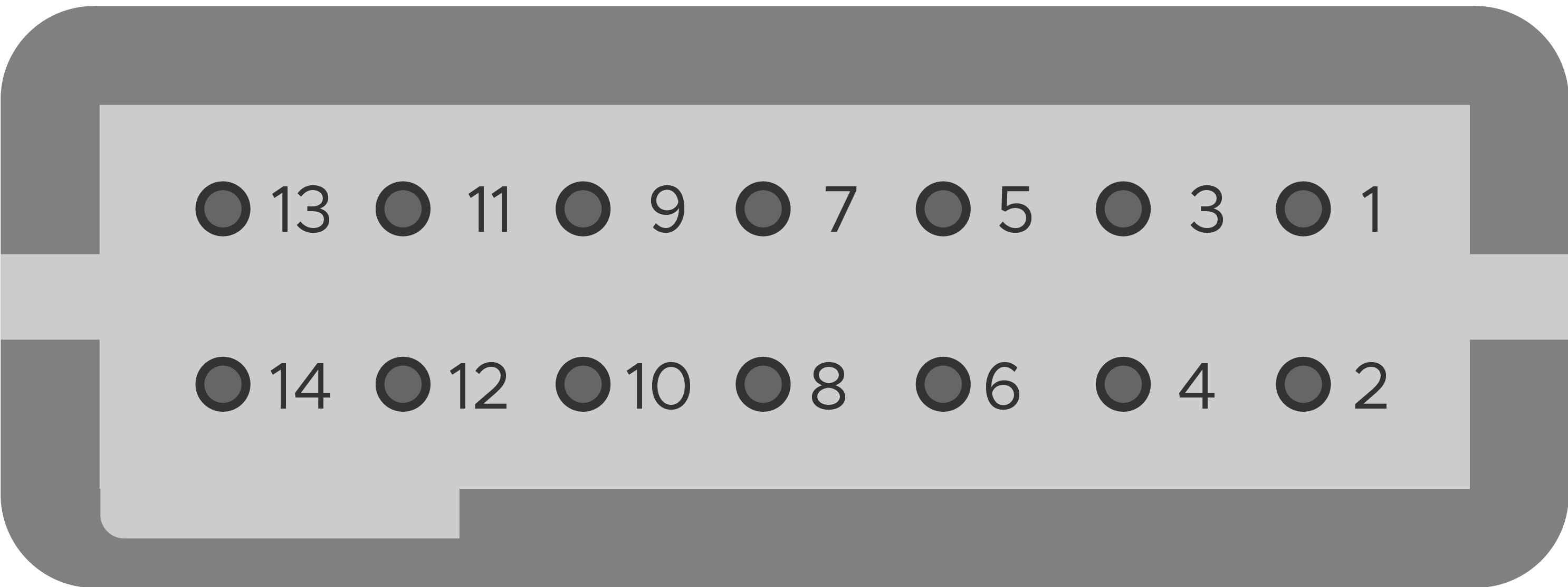
Kāhu interlock connector pinout, viewed from the back
Cable Part No. |
|
|---|---|
Pin No. |
Function |
1, 3, 5, 7, 9 |
GND |
2 |
5 V TTL Shim interlock Output |
4, 6, 8, 10 |
5 V TTL Gradient interlock Outputs |
11-14 |
NC (reserved) |
Shim Controller
The pinout of the shim connector is as follows:
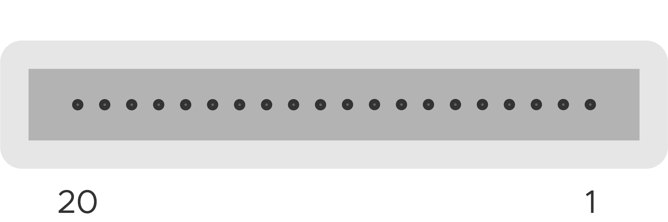
Kāhu shim connector pinout, viewed from the back
Cable Part No. |
|
|---|---|
Pin No. |
Shim Channel Index |
1 |
0 |
2 |
1 |
3 |
2 |
4 |
3 |
5 |
4 |
6 |
5 |
7 |
6 |
8 |
15 |
9 |
14 |
10 |
13 |
11 |
12 |
12 |
11 |
13 |
10 |
14 |
9 |
15 |
8 |
16 |
7 |
17 - 20 |
NC |
Caution
When plugging in the shim cable to Kāhu ensure the gold contacts are facing upwards.
Temperature control
Kāhu provides capability to monitor and control temperature through the PT100 connector. Two sensor inputs can be connected and then used to automatically control the duty cycle of their respective PWM outputs to achieve a stable temperature. The two channels maybe be operated independently or in conjuction. Each PWM signal is 5 V and can be used to control a heater, fan, or peltier module.
In the JupyterLab environment, the temperature can be monitored and the PID settings adjusted using the System dashboard app, see Temperature Monitor.
The pin configuration for the PT100 connector is:
Cable Part No. |
|
|---|---|
Pin No. |
Function |
1 |
PT100 2 Reference |
2 |
PT100 1 Reference |
3 |
PT100 2 + |
4 |
PT100 1 + |
5 |
PT100 2 - |
6 |
PT100 1 - |
7, 8 |
GND |
9 |
PWM 1, 5 V output |
10 |
PWM 2, 5 V output |
The diagram below illustrates the connector pinout and an example of how to connect a PT100 sensor to Kāhu. Note that the reference wire should connect at the sensor itself so that it is the same length/resistance as the ‘-’ connection (3-wire PT100 configuration).
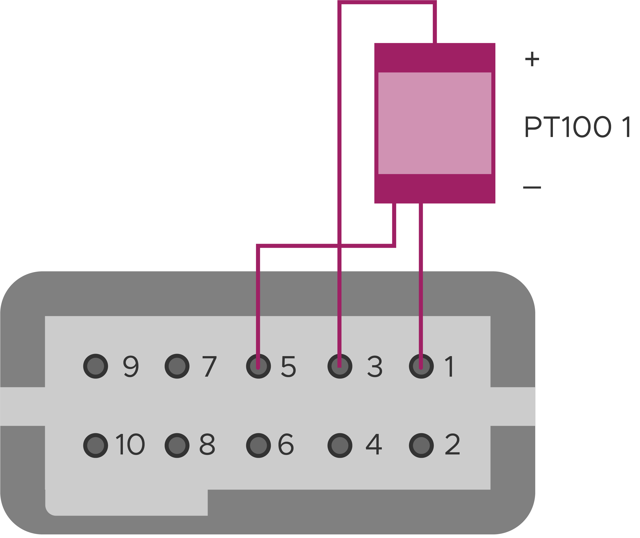
PT100 Sensor 1 Wiring Diagram
Typical Performance Characteristics
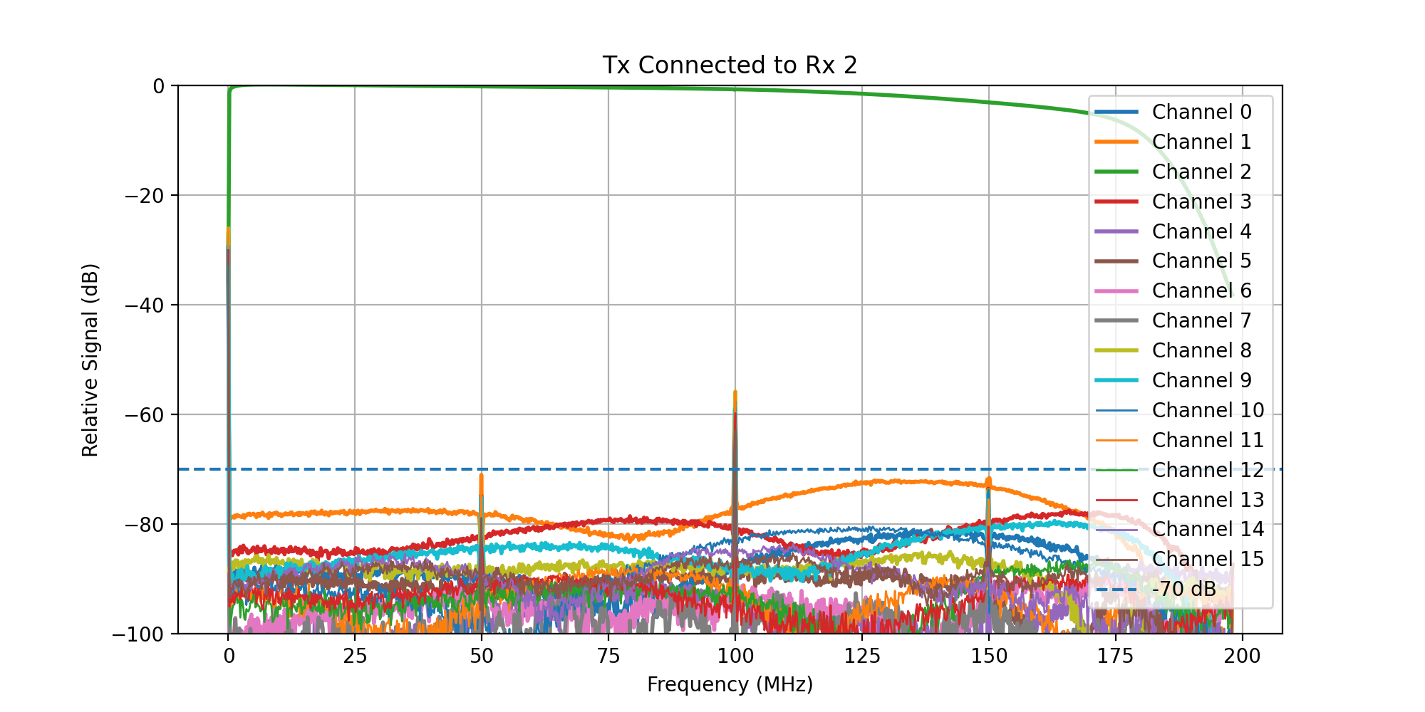
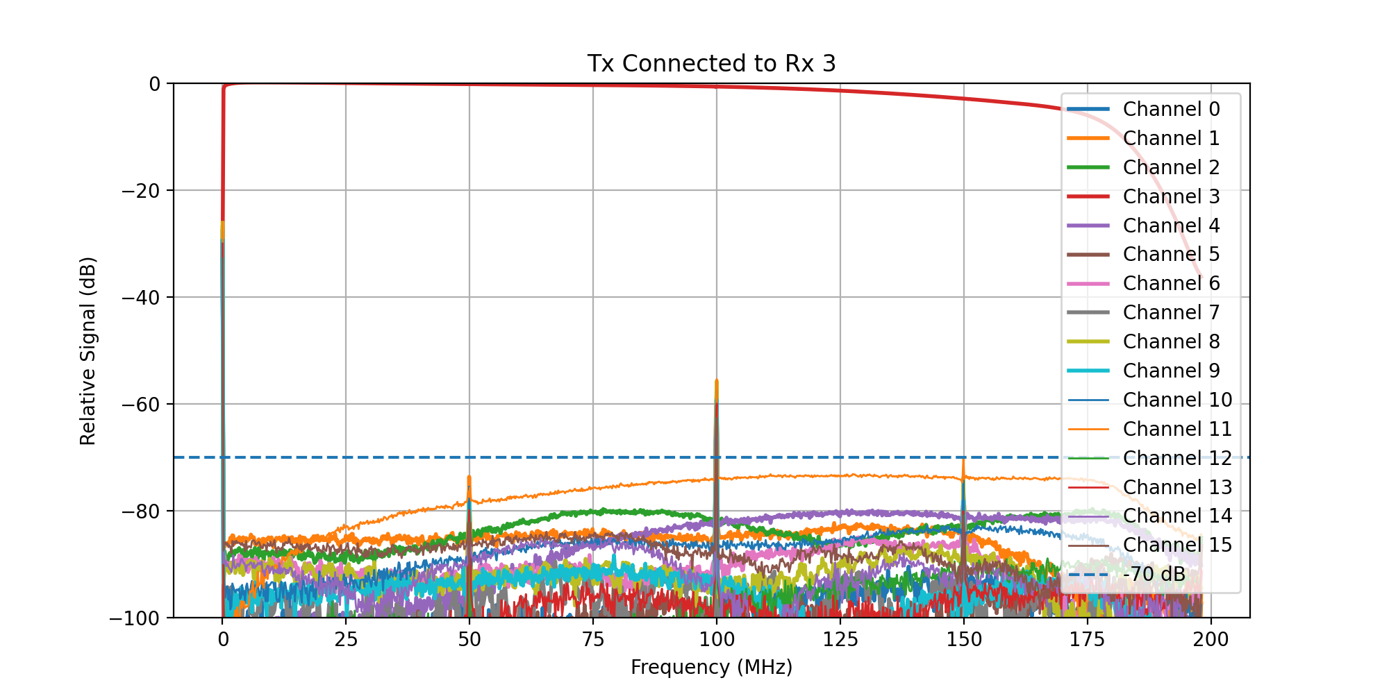
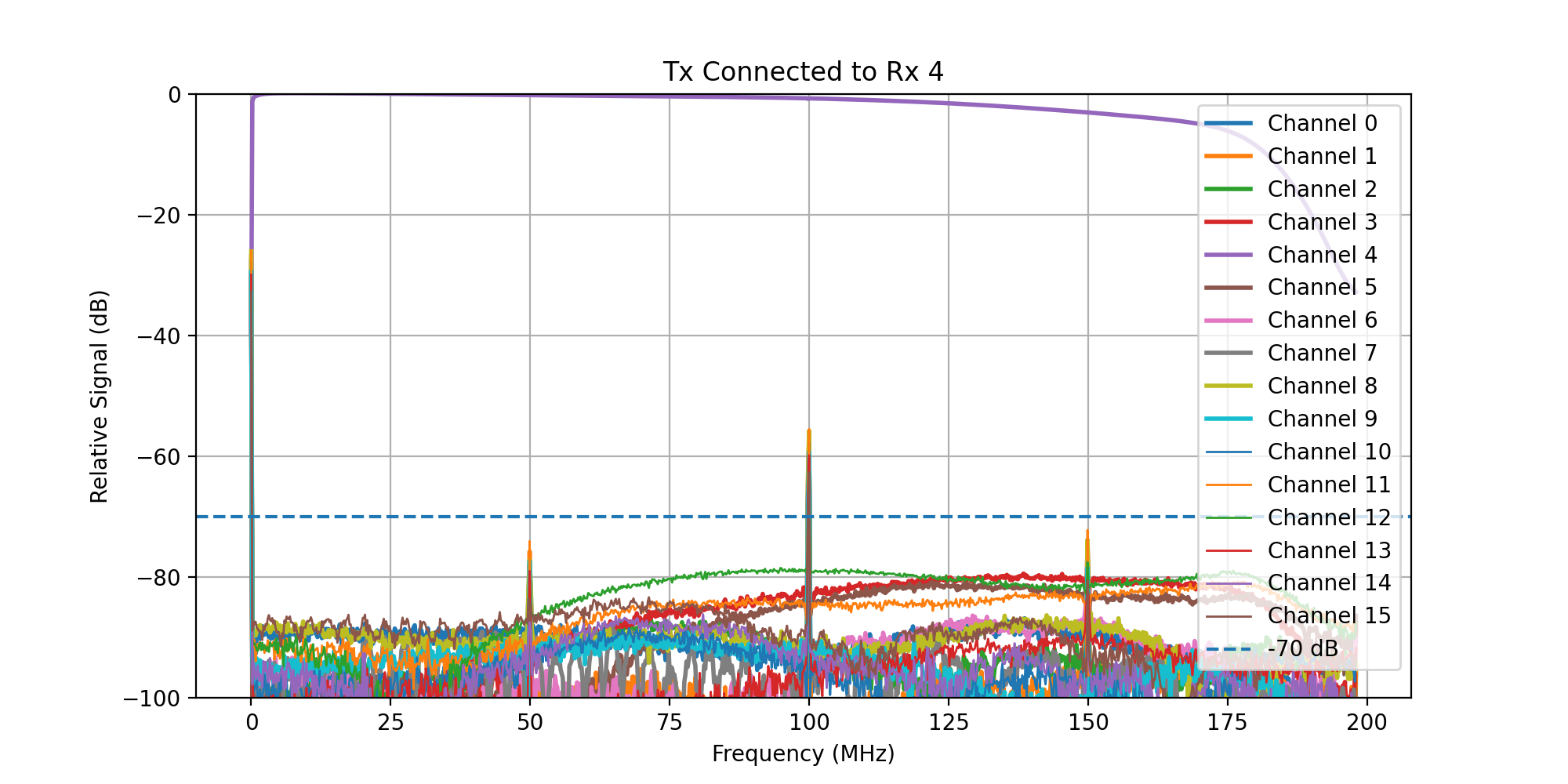
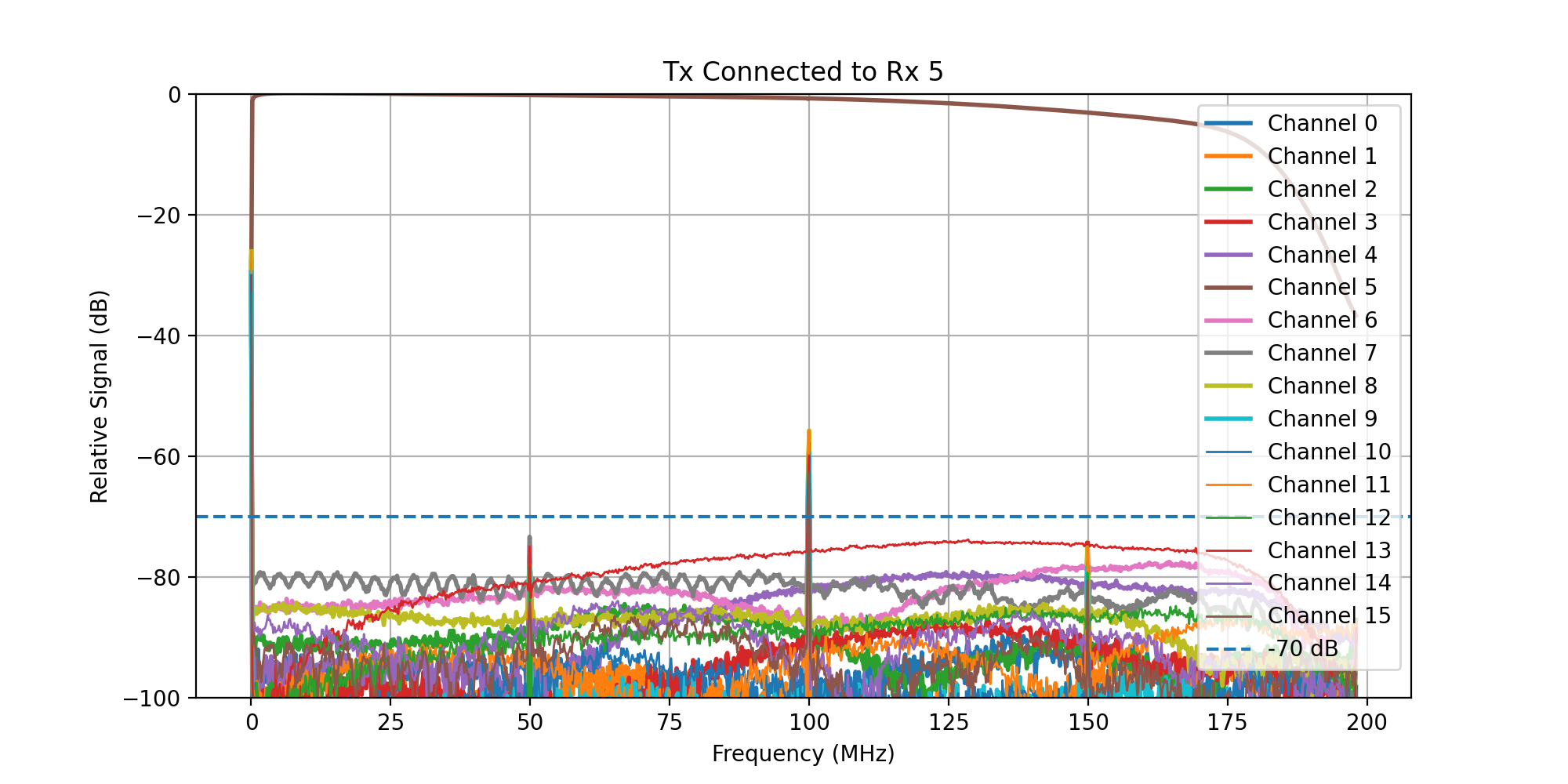
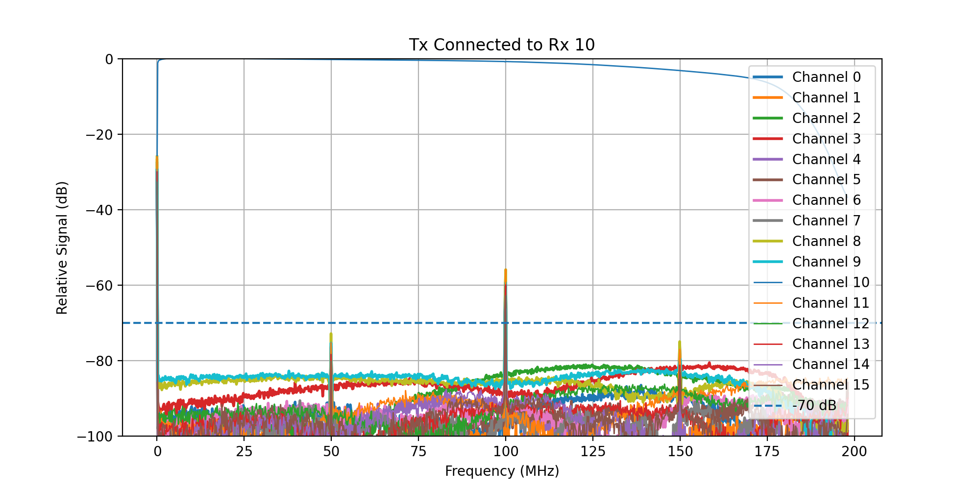
Crosstalk Measurement Setup
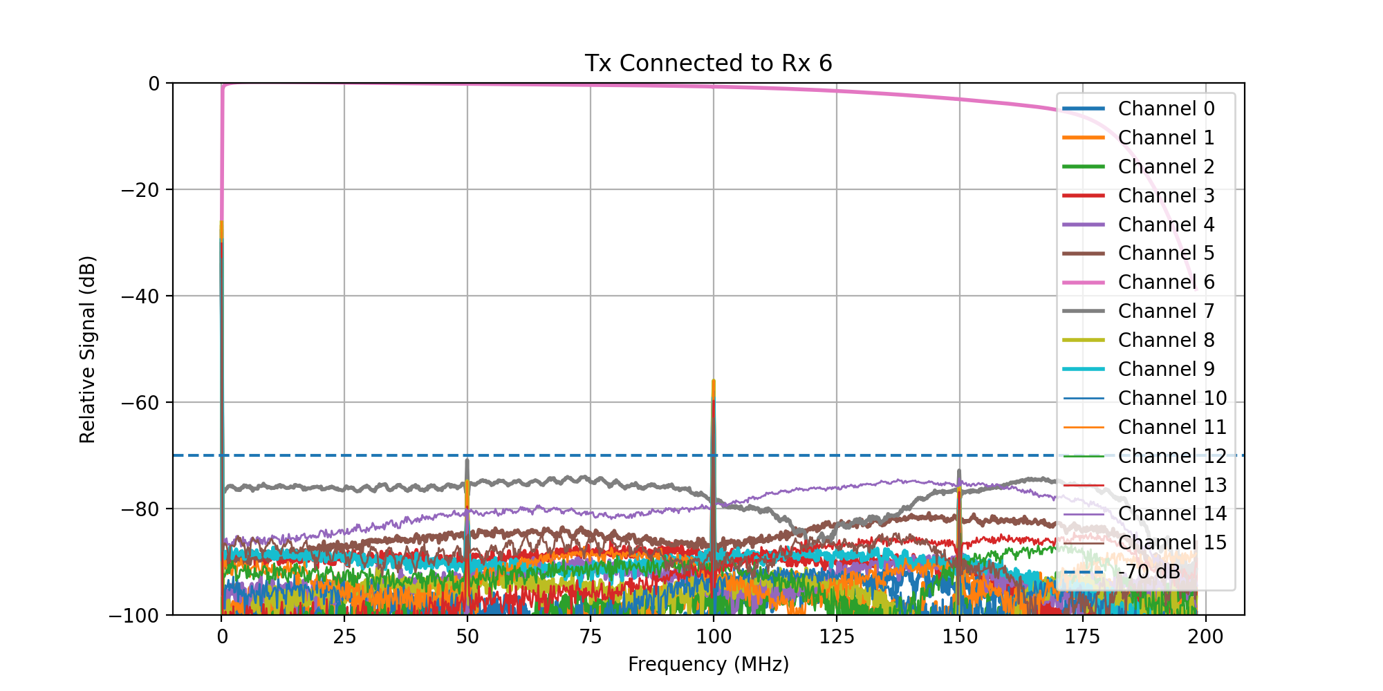
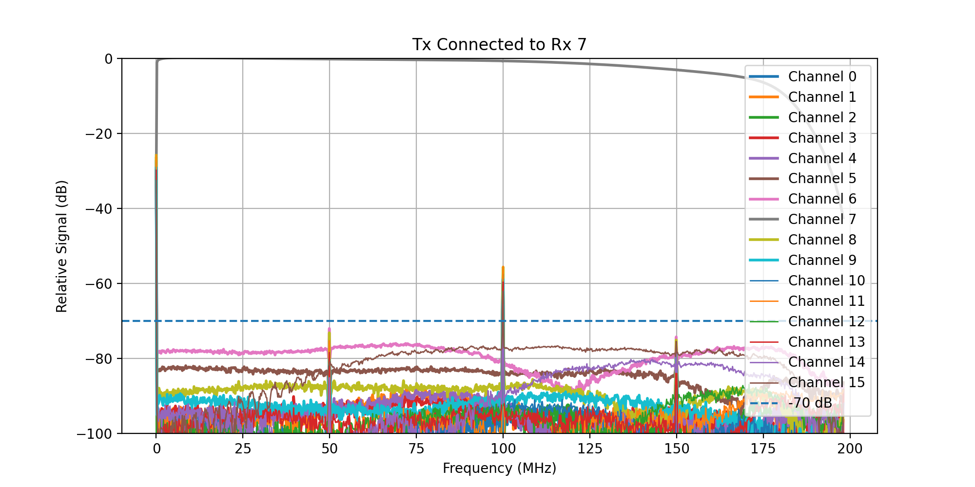
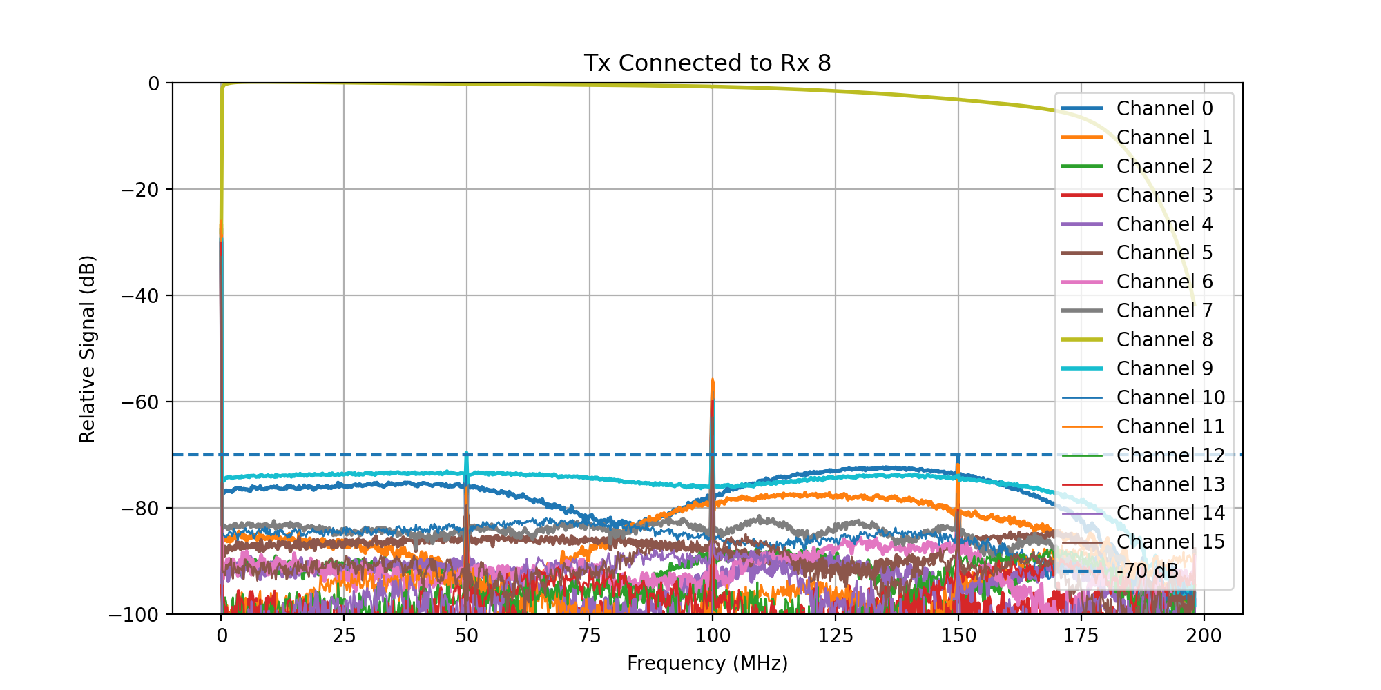
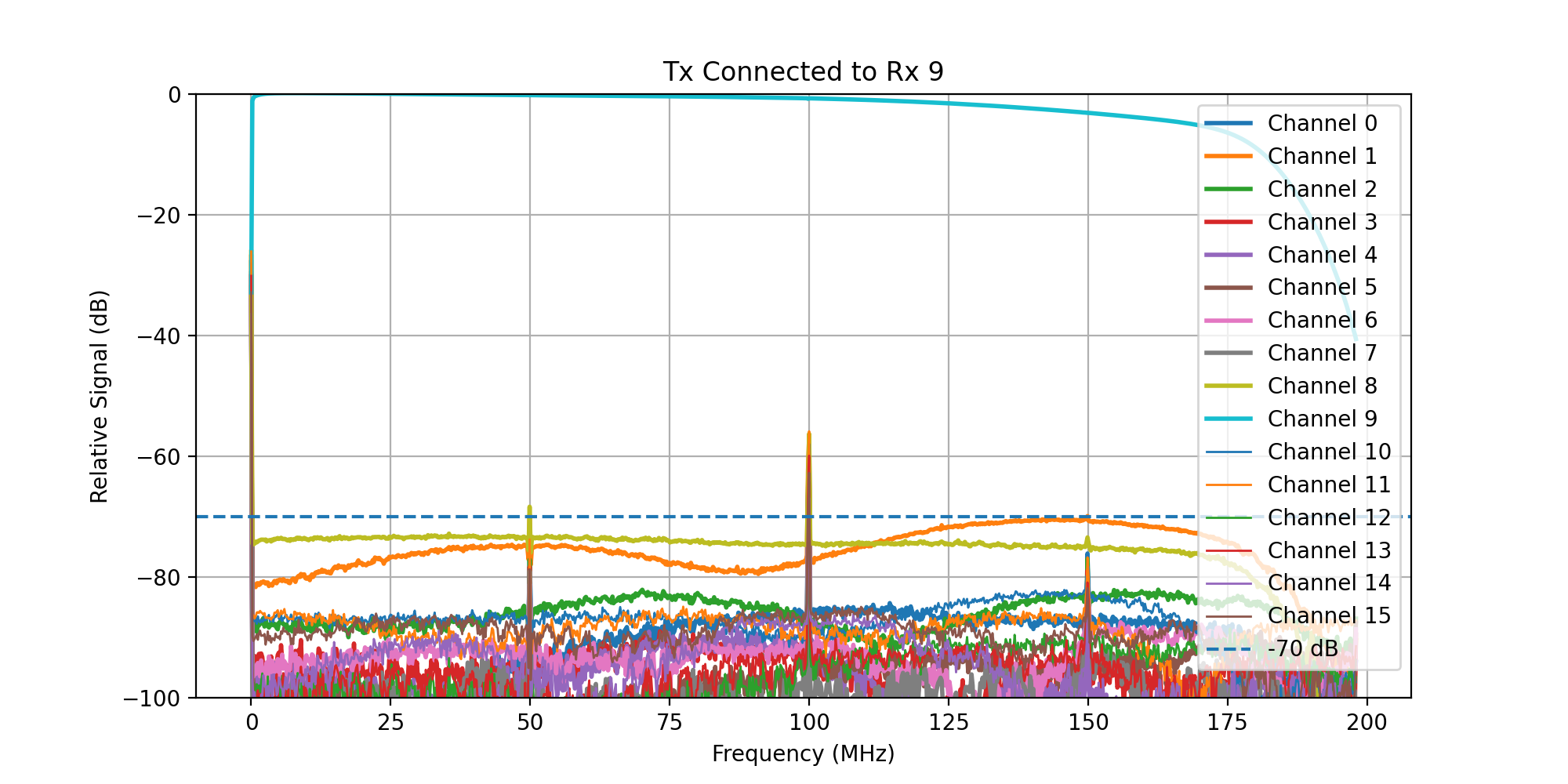
The crosstalk has been characterised by connecting Transmit channel 0 to each Rx channel in turn with a coaxial cable and transmitting a frequency sweep while acquiring on all Rx channels. Unconnected Rx channels were left unterminated for this test.
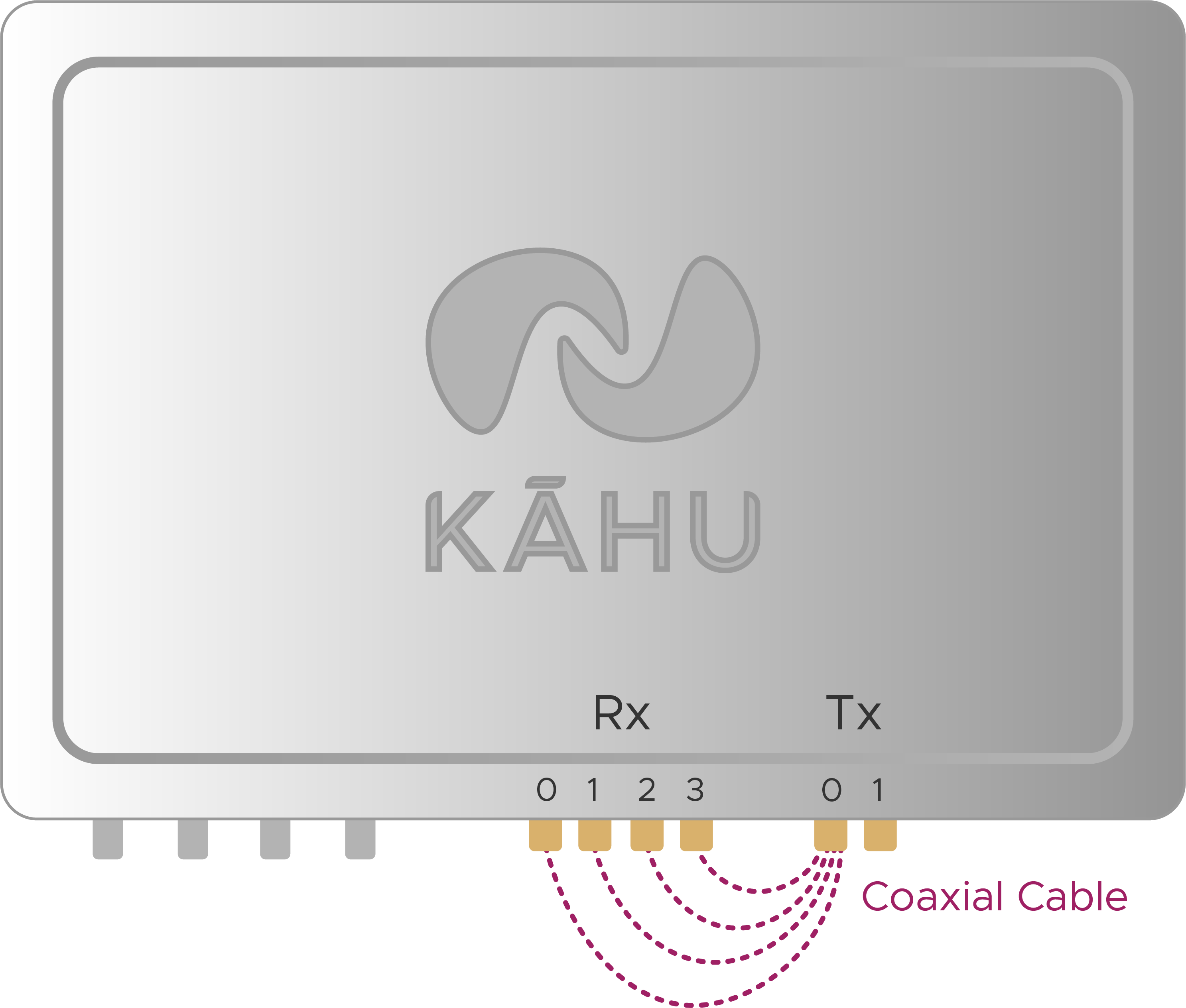
Crosstalk Measurement Setup
A frequency sweep from 0 - 200 MHz was then transmitted, while acquiring signal on all Rx channels.
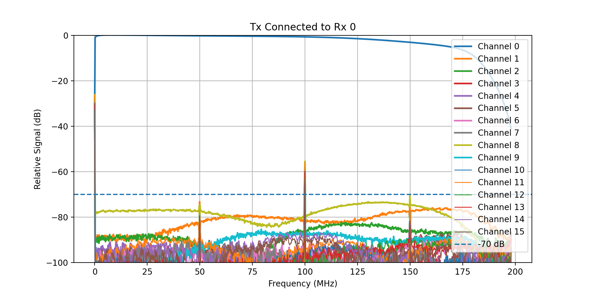
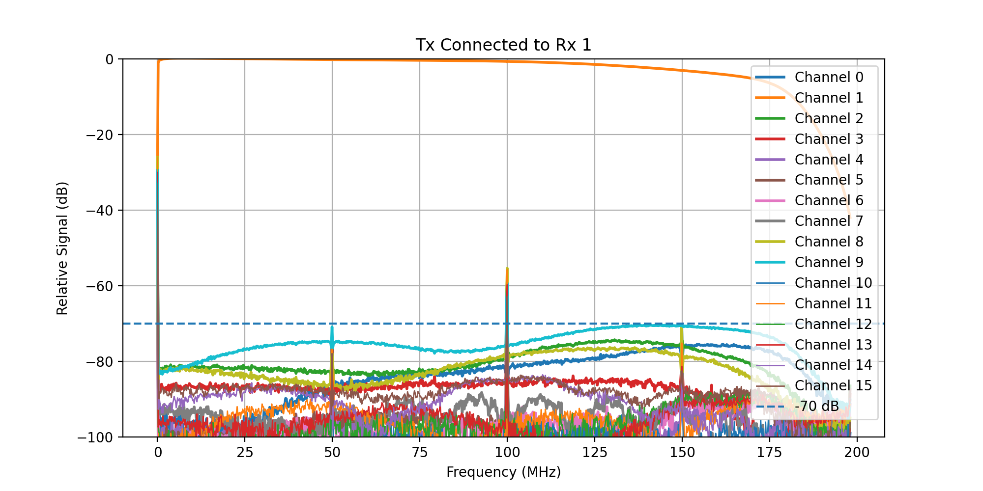
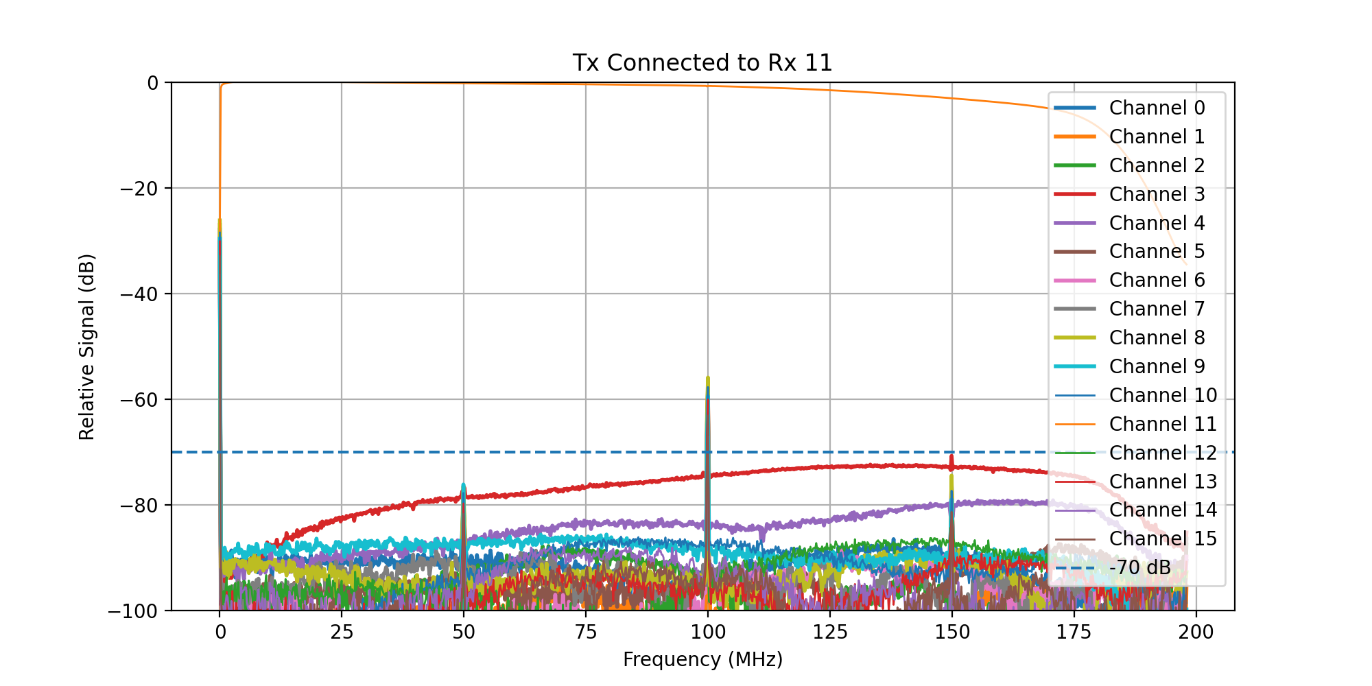
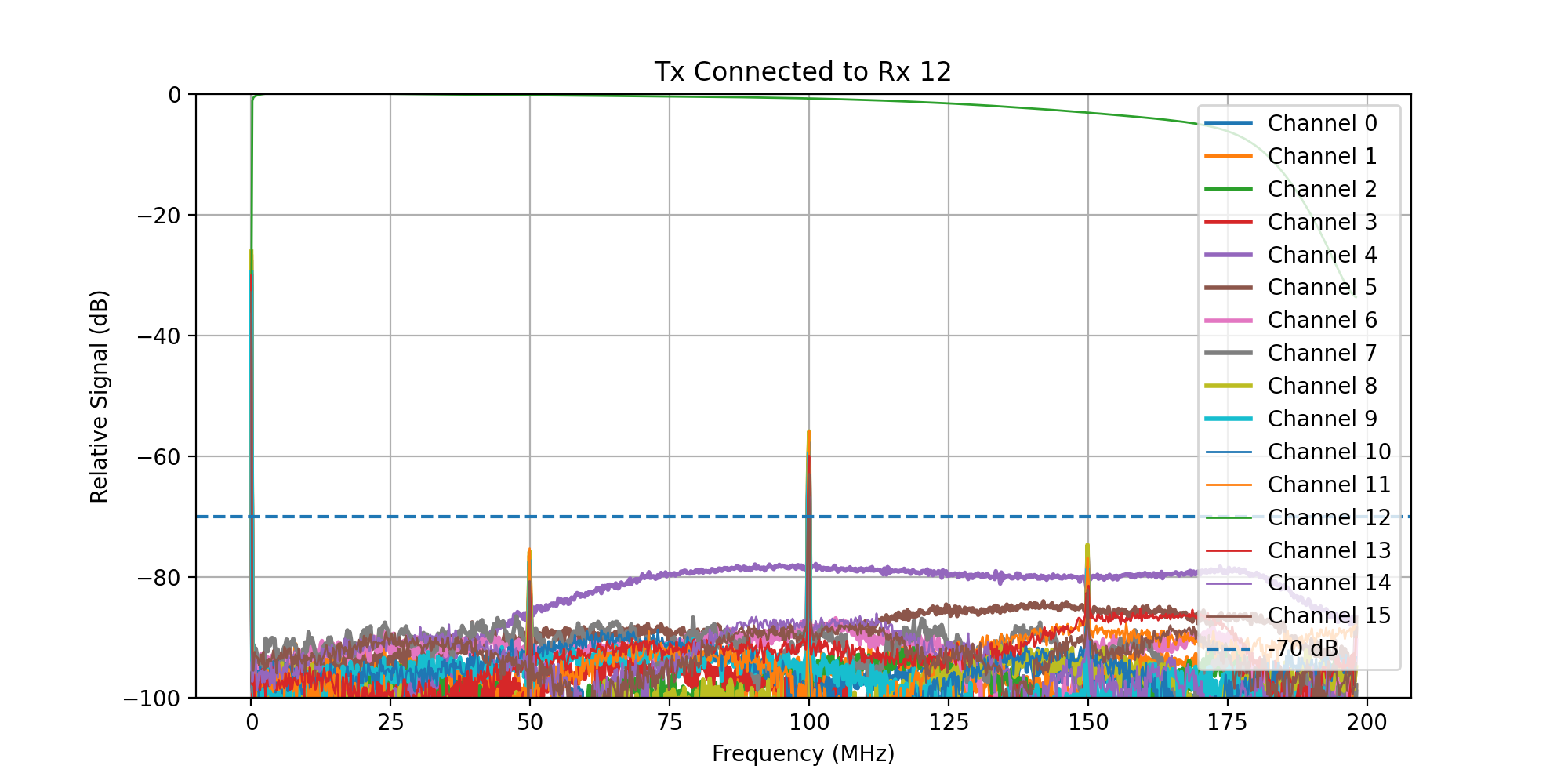
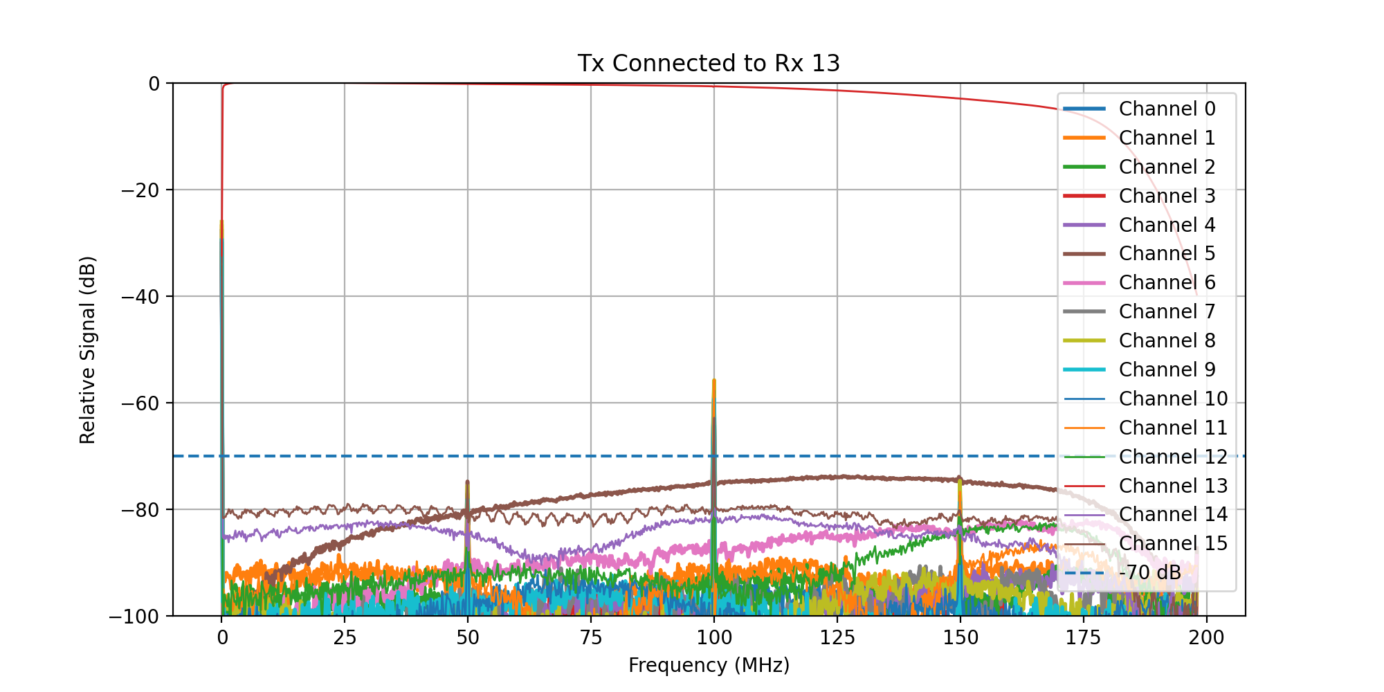
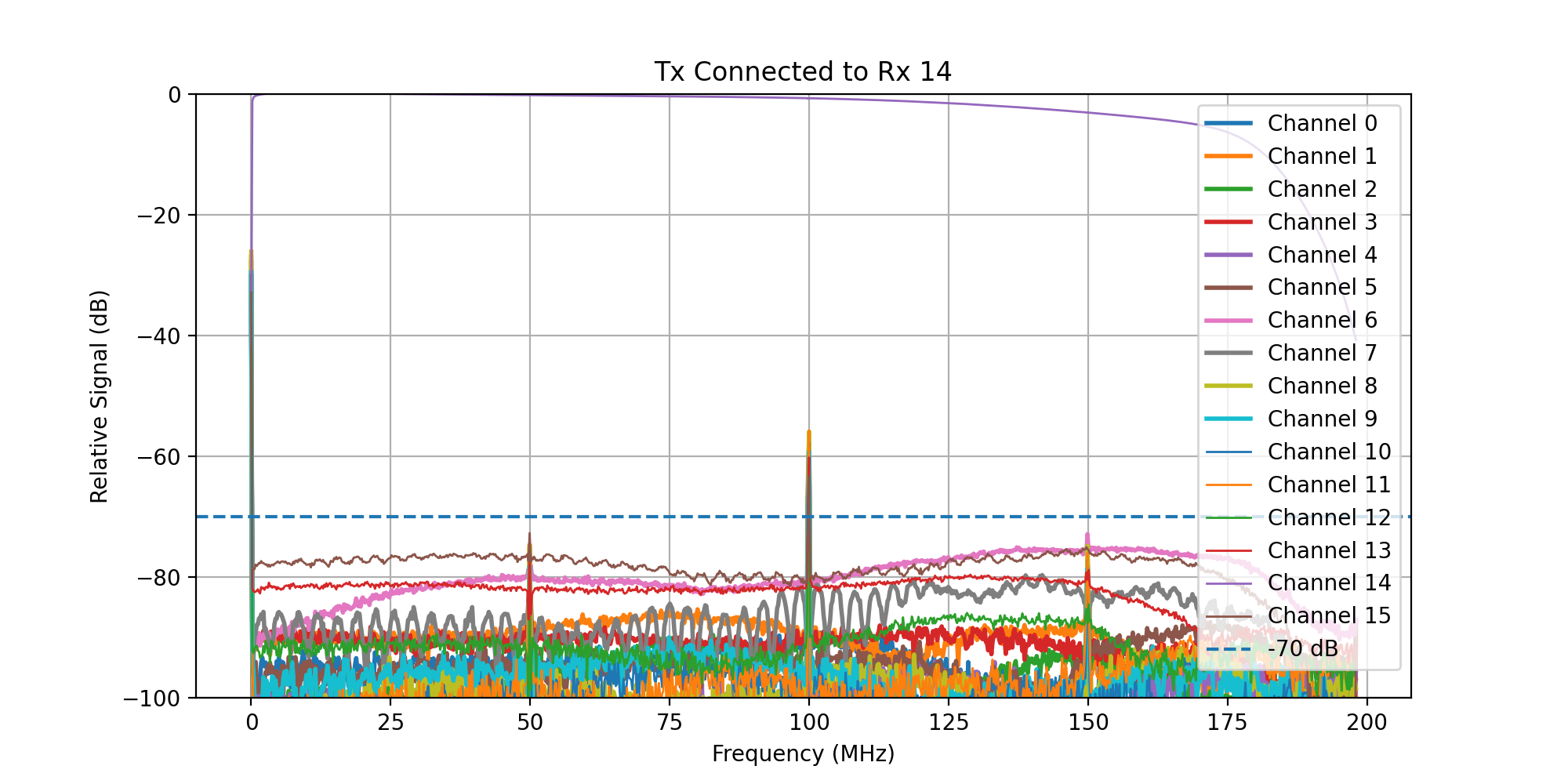
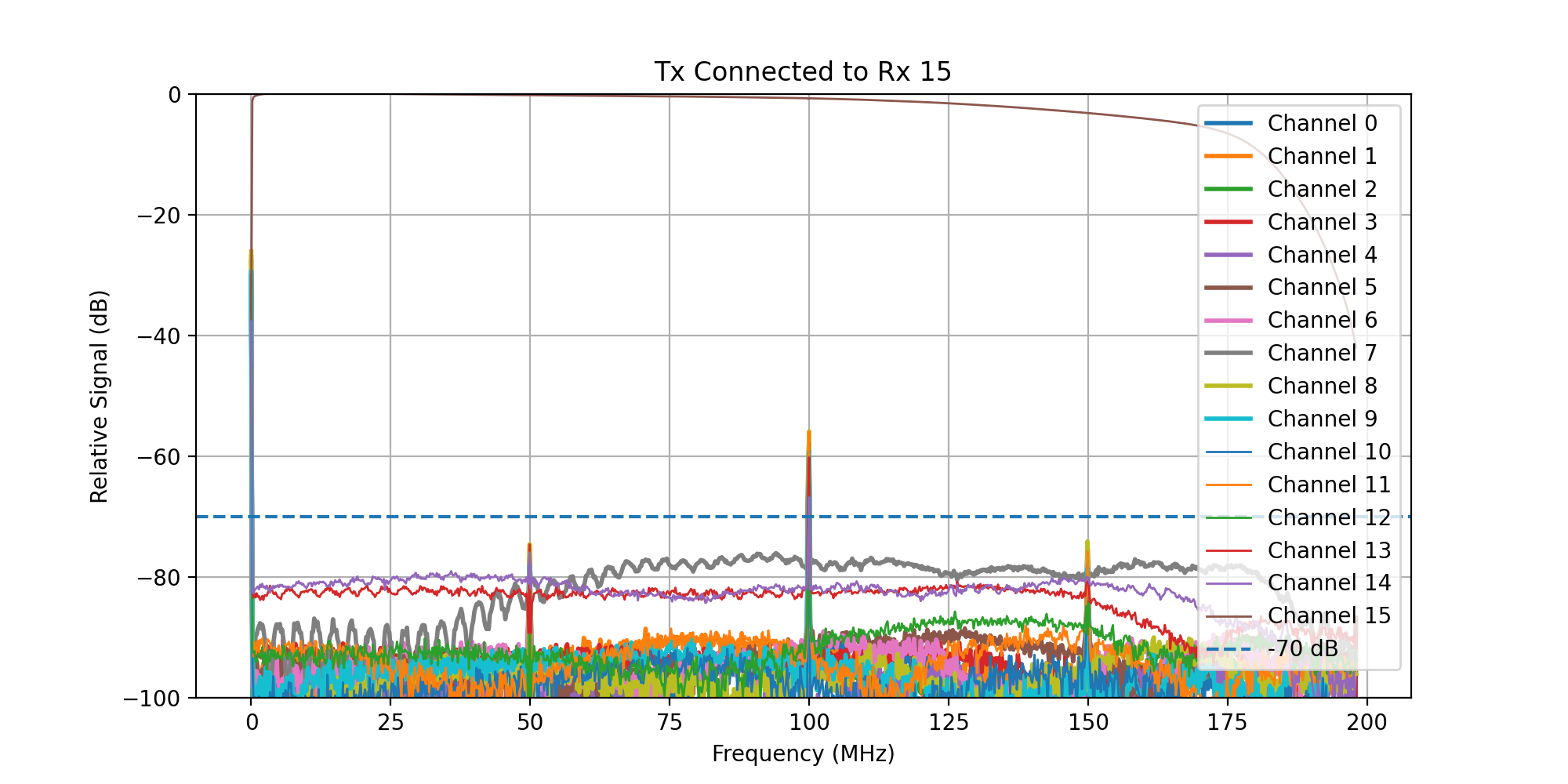
Crosstalk 16-Channel
The following plots show test results measured on the 16-channel Kāhu. Note that the sampling rate of the 16-channel Kāhu is 50 MSPS, which causes spikes at mutliples of 50 MHz due to the aliasing of the DC offset.
Crosstalk 4-Channel
The 4-channel Kāhu crosstalk measurements are summarised below:
Rx loopback channel |
Rx 0 dB |
Rx 1 dB |
Rx 2 dB |
Rx 3 dB |
|---|---|---|---|---|
0 |
0 |
-85 |
-90 |
-100 |
1 |
-85 |
0 |
-100 |
-105 |
2 |
-105 |
-95 |
0 |
-83 |
3 |
-100 |
-100 |
-80 |
0 |